Special fixture for mounting high-speed camera of ultra-precision machine tool

A technology of ultra-precision machine tools and high-speed cameras, which is applied in the direction of manufacturing tools, metal processing machinery parts, measuring/indicating equipment, etc., can solve inconvenience and other problems, and achieve the effect of wide adjustment range, high adjustment accuracy and multiple adjustment angles

Active Publication Date: 2021-06-15
HARBIN INST OF TECH
View PDF7 Cites 0 Cited by
  • Summary
  • Abstract
  • Description
  • Claims
  • Application Information

AI Technical Summary

Problems solved by technology

[0003] Due to the different structures of different machine tools and different key parts that need to be photographed, the placement of high-speed cameras is different. For example, a machine tool with a horizontal spindle generally requires a high-speed camera to shoot vertically, while a machine tool with a vertical spindle requires a high-speed camera to shoot horizontally. It is very inconvenient to use multiple sets of fixtures

Method used


Image

  • Special fixture for mounting high-speed camera of ultra-precision machine tool
  • Special fixture for mounting high-speed camera of ultra-precision machine tool
  • Special fixture for mounting high-speed camera of ultra-precision machine tool

Examples


Embodiment 1

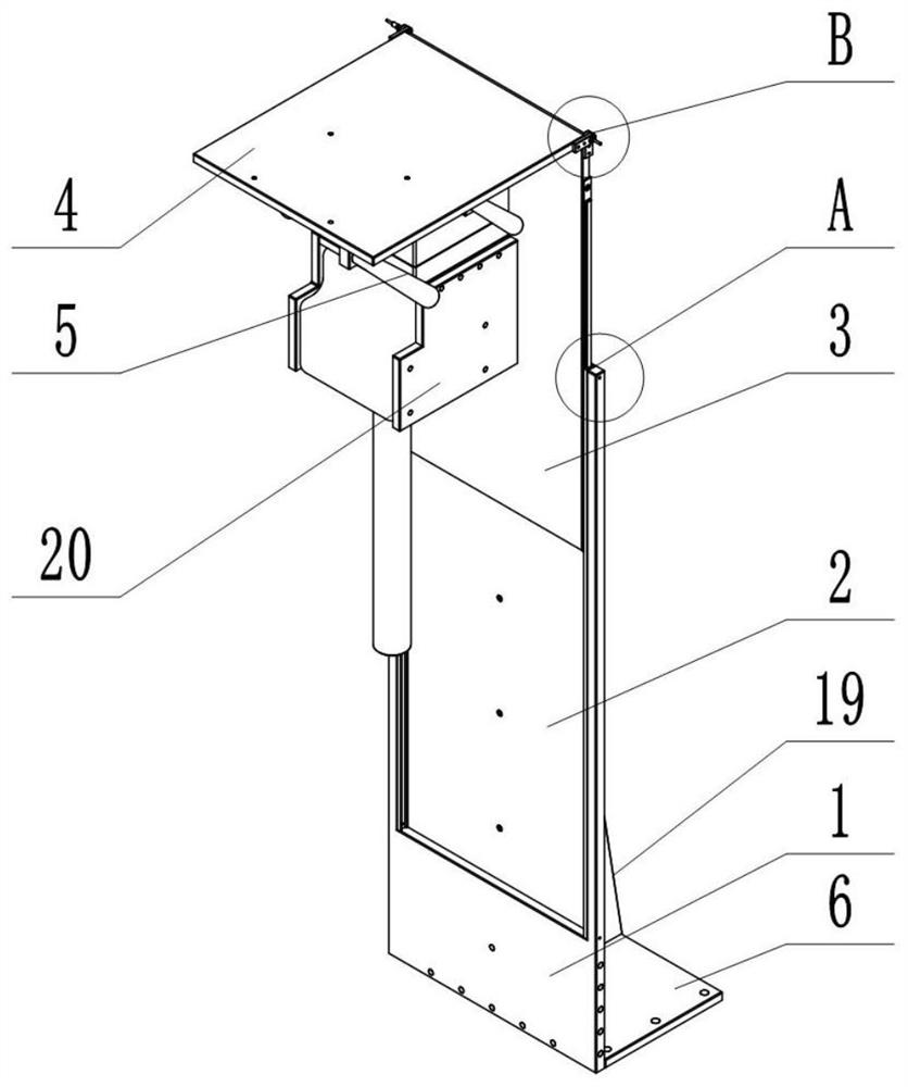
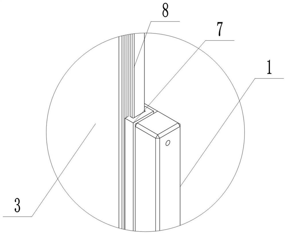
[0033] refer to Figure 1-6 , the present invention provides a special fixture for the installation of high-speed cameras for ultra-precision machine tools, including a lower vertical plate 1 of the fixture, a chute 2 is longitudinally opened on the top surface of the lower vertical plate 1 of the fixture, and an upper vertical plate of the fixture is slidably connected in the chute 2 3;

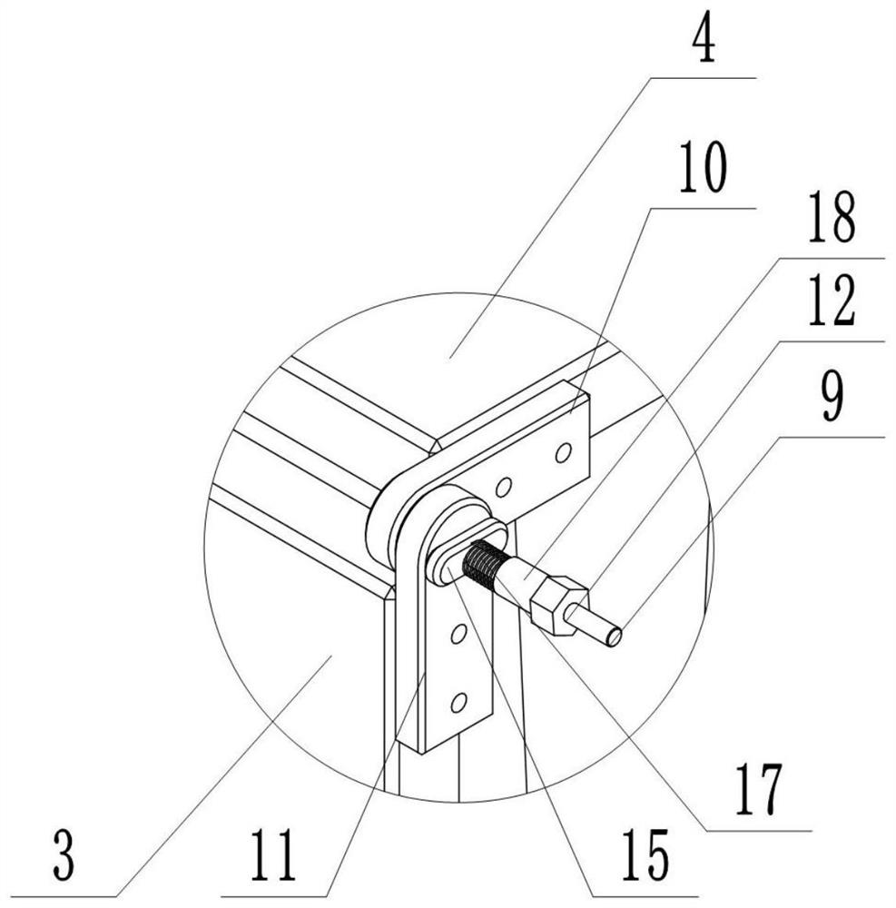
[0034] The top of the fixture upper vertical plate 3 is rotated to connect the fixture upper top plate 4, and a self-locking hinge assembly is arranged between the fixture upper vertical plate 3 and the fixture upper top plate 4;

[0035] A three-degree-of-freedom micro-displacement platform 5 is fixedly connected to one end surface of the upper top plate 4 of the fixture. The upper top plate 4 of the fixture is provided with a number of installation holes for fine-tuning the installation position of the three-degree-of-freedom micro-displacement platform 5. The three-degree-of-freedom micro...

Embodiment 2

[0048] refer to Figure 7 , the difference between this embodiment and Embodiment 1 is that the device is installed horizontally, the lower vertical plate 1 of the fixture is vertically fixed to the side of the additional base plate 21 of the clamp, and then the additional base plate 21 of the clamp is fixed with the high-speed machine tool, so that the device Horizontally installed and fixed; several screw holes are reserved on the upper vertical plate 3 of the fixture, and the three-degree-of-freedom micro-displacement platform 5 is fixed on the upper vertical plate 3 of the fixture, and the high-speed camera fixing frame 20 is installed with reference to the method of embodiment 1 here and high-speed cameras.

[0049] In this installation method, the adjustment method of the Z-axis direction is the same as that of the X-axis direction in Embodiment 1, the adjustment method of the X-axis direction is the same as that of the Z-axis direction in Embodiment 1, and the adjustmen...

Embodiment 3

[0052] refer to Figure 8-11 The difference between this embodiment and Embodiment 1 is that the lower vertical plate 11 of the fixture in this embodiment is provided with an inner shaft 22, the inner shaft 22 is located below the chute 2, and the inner shaft 22 is covered with two sections of outer shafts 26. The inner shaft 22 is rotationally connected with the outer shaft 26; two first bevel gears 27 are sleeved on the inner shaft 22, and a second bevel gear 28 is respectively sleeved on the two sections of the outer shaft 26, wherein the two first bevel gears The gears are respectively affixed to the inner shaft 22, and the two second bevel gears 28 are respectively affixed to the two sections of the outer shaft 26; two longitudinal screw rods 23 are arranged above the inner shaft 22, and a slider 25 is threadedly connected to the screw rod 23, The slider 25 is fixedly connected with the upper vertical plate 3 of the fixture; the end of the screw rod near the inner shaft 2...


PUM


Abstract

The present invention provides a special fixture for mounting a high-speed camera used for dynamically monitoring a high-speed machining process of an ultra-precision machine tool. The special fixture includes a fixture lower vertical plate, the fixture lower vertical plate is slidably connected with a fixture upper vertical plate, the top end of the fixture upper vertical plate is rotatably connected with a fixture upper top plate, and a self-locking hinge assembly is arranged between the fixture upper vertical plate and the fixture upper top plate. The fixture upper top plate is fixedly connected with a three-degree-of-freedom micro-displacement platform, the bottom surface of the three-degree-of-freedom micro-displacement platform is fixedly connected with a high-speed camera fixing frame, and the end, away from the fixture upper vertical plate, of the fixture lower vertical plate is perpendicularly provided with a fixture bottom plate. Compared with the prior art, the special fixture achieves fine adjustment of a lens of the high-speed camera in all directions and coarse-fine combined adjustment in a vertical direction, achieves rotation of the lens of the high-speed camera from 0 DEG to 360 DEG, has the function of self-locking every other angles, has the characteristics such as multiple adjusting angles, wide adjusting range, and high adjusting precision, and is suitable for meeting a shooting requirement of dynamic monitoring in machining processes of ultra-precision machine tools with different layout characteristics.

Description

technical field [0001] The invention relates to the technical field of ultra-precision machining, in particular to a special fixture for installing a high-speed camera of an ultra-precision machine tool. Background technique [0002] The ultra-precision diamond turning machine tool has extremely high motion accuracy, can achieve a cutting depth of several microns or even sub-microns, has extremely high machining accuracy and extremely low sub-surface damage, and is a kind of ultra-smooth surface for preparing various materials important means. Since the cutting depth is on the order of microns and the workpiece speed is 3000 rpm, it is difficult for the naked eye to capture the phenomena of material removal and chip formation in the ongoing turning process, resulting in the failure of many related theoretical models to be verified, which limits the ultra-precision diamond Improvement of turning precision. With the continuous upgrading of optical imaging components and the ...

Claims


Application Information

Patent Timeline
IPC IPC(8): B23Q17/24
CPCB23Q17/2409
Inventor 张俊杰刘士荃张海军张春雨卢仕进宋成伟赵梁李国孙涛
Owner HARBIN INST OF TECH
Why Eureka
Try Eureka