
Nitrogen oxidation furnace

A technology of nitrogen oxidation furnace and furnace body, applied in metal material coating process, coating, solid diffusion coating and other directions, can solve the problems of slow cooling speed, large gas consumption, long time consumption, etc., to improve cooling speed, reduce The effect of consumption and ease of operation

Pending Publication Date: 2021-06-15
SHANGHAI SHIJIN NEW MATERIAL TECH
View PDF5 Cites 0 Cited by
  • Summary
  • Abstract
  • Description
  • Claims
  • Application Information

AI Technical Summary

Problems solved by technology

Therefore, at present, many nitriding furnaces also have the function of oxidation, forming a nitrogen oxidation furnace. Superheated steam is usually used as the gas source for oxidation, but an additional heating device is required in the process of generating water vapor from superheated steam, resulting in a high risk factor. , large energy consumption
And the heating process is usually indirect heating, which leads to the slow cooling rate of the mold workpiece in the nitrogen oxidation furnace during the nitriding process, which affects the nitriding effect
[0005] In order to avoid the above deficiencies, some nitrogen oxidation furnaces use fans to blow ammonia gas to cool down the mold workpieces, but the method of blowing ammonia gas with fans consumes a lot of gas and takes a long time. Some nitrogen oxidation furnaces use nitrogen A separate cooling fan is added outside the furnace body of the oxidation furnace, but after the mold workpiece is cooled to a certain temperature, it is difficult to continue cooling the mold workpiece through the cooling fan, which cannot meet the demand standard of the mold workpiece

Method used


Image

  • Nitrogen oxidation furnace

Examples


Embodiment Construction

[0031] Specific embodiments of the present invention will be described in detail below in conjunction with the accompanying drawings. It should be understood that the specific embodiments described here are only used to illustrate and explain the present invention, and are not intended to limit the present invention.

[0032] In the present invention, unless stated to the contrary, the used orientation words such as "upper, inner, outer" generally refer to upper, inner, outer as shown in the attached drawings.

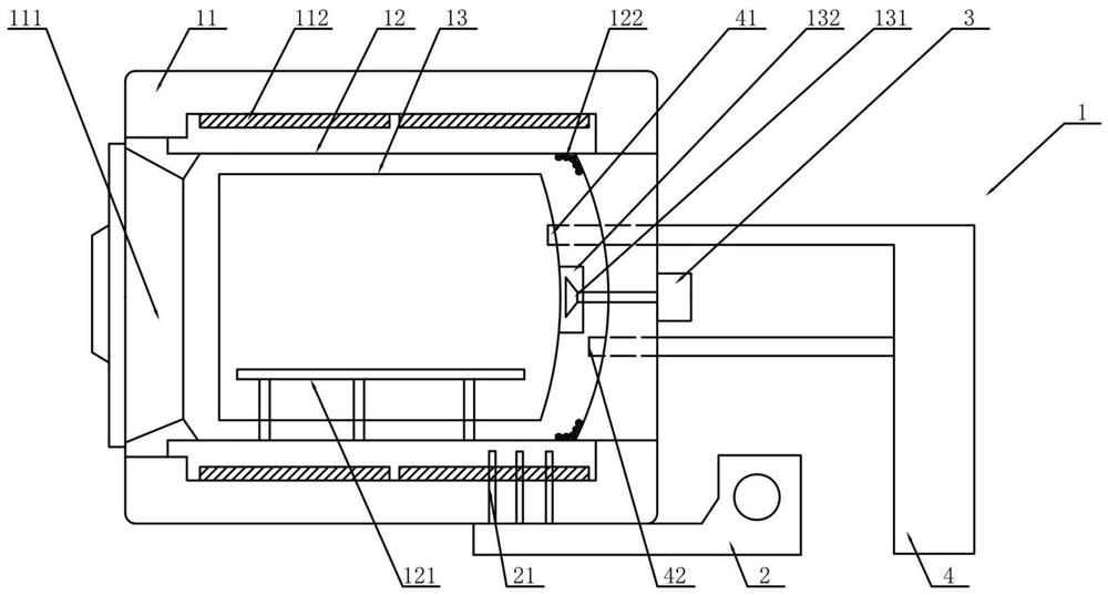
[0033] The present invention provides a nitrogen oxidation furnace, please refer to figure 1 As shown, a furnace body 1 is included, and the furnace body includes an outer shell 11, an inner shell 12 and an air guide tube 13, the outer shell 11 is provided with a furnace door 111, and the inner shell 12 is arranged in the outer shell 11, so The air guide tube 13 is arranged in the inner shell 12. Preferably, a certain space can be left between the inner shell 12 and t...


PUM


Abstract

The invention relates to the field of nitrogen oxidation equipment, and discloses a nitrogen oxidation furnace. The nitrogen oxidation furnace comprises a furnace body, wherein the furnace body comprises an outer shell, an inner shell and an air guide barrel, a furnace door is arranged on the outer shell, the inner shell is arranged in the outer shell, the air guide barrel is arranged in the inner shell, a material frame support is arranged in the inner shell and extends into the air guide barrel, a heating pipe is arranged in the outer shell, and the heating pipe is arranged in the inner shell. A steam evaporation pipe is arranged in the inner shell, a draught fan is arranged on the outer side of the air guide barrel, and steam enters the air guide barrel through the draught fan. The furnace has the beneficial effects that one furnace can be used for multiple purposes; an additional heating device does not need to be configured; forced cooling of the die workpiece subjected to nitriding oxidation treatment in the furnace body is achieved, meanwhile, the cooling speed of the die workpiece is increased, and the requirement standard of the die workpiece can be met; the nitrogen oxidation furnace is space-saving and convenient to operate, and workpiece in-out furnace efficiency can be effectively improved.

Description

technical field [0001] The invention relates to the field of nitrogen oxidation equipment, in particular to a nitrogen oxidation furnace. Background technique [0002] During the long-term use of the mold, surface failure often occurs, and the causes of surface failure are such as wear, corrosion or thermal melting loss. In order to avoid surface failure as much as possible, at present, people usually use the method of nitriding the mold surface in advance during mold production. The mold surface after nitriding treatment can effectively avoid the occurrence of mold surface failure. Because after the nitriding treatment is carried out on the surface of the mold, a nitriding layer will be formed on the surface of the mold, and the nitriding layer improves the hardness of the surface of the mold, and also enhances the corrosion resistance and wear resistance of the mold. [0003] At present, nitriding furnaces are usually used as equipment for nitriding molds, but most of the...

Claims


Application Information

Patent Timeline
IPC IPC(8): C23C8/34C23C8/80
CPCC23C8/34C23C8/80
Inventor 吴晓春
Owner SHANGHAI SHIJIN NEW MATERIAL TECH
Learn More