
Measurement method for quasi-static stress deformation in large-view-field plane

A technology of force deformation and measurement method, which is applied in the direction of measuring devices, graphics and image conversion, details involving image splicing, etc., can solve the problems of difficulty in reflecting the whole picture of deformation, decline in measurement accuracy, and difficulty in convenient application, etc., to achieve the production of black and white spots at will , Simplify the difficulty and realize the simple effect

Active Publication Date: 2021-06-15
XIAN UNIV OF TECH
View PDF4 Cites 0 Cited by
  • Summary
  • Abstract
  • Description
  • Claims
  • Application Information

AI Technical Summary

Problems solved by technology

However, the photogrammetry method, the measurement results obtained are only the deformation information of each key position, and it is difficult to reflect the whole picture of the deformation.
And the algorithm is complex to implement
The three-dimensional digital image correlation method can obtain the whole picture of deformation in three directions, but the resolution of the camera is difficult to adapt to the large measurement field of view. If a short-focus lens is used to observe the whole picture, there are requirements for the preparation of spots and the large field of view The camera calibration process is complicated, resulting in a decrease in measurement accuracy
If multiple cameras are used to observe the final stitching of each surface, the calibration of multiple cameras is another problem
In addition, it also needs the support of 3D reconstruction algorithm, which is difficult to be conveniently applied in actual measurement

Method used


Image

  • Measurement method for quasi-static stress deformation in large-view-field plane
  • Measurement method for quasi-static stress deformation in large-view-field plane
  • Measurement method for quasi-static stress deformation in large-view-field plane

Examples


Embodiment Construction

[0036]A method for measuring quasi-static force deformation in a plane with a large field of view, comprising the following steps:

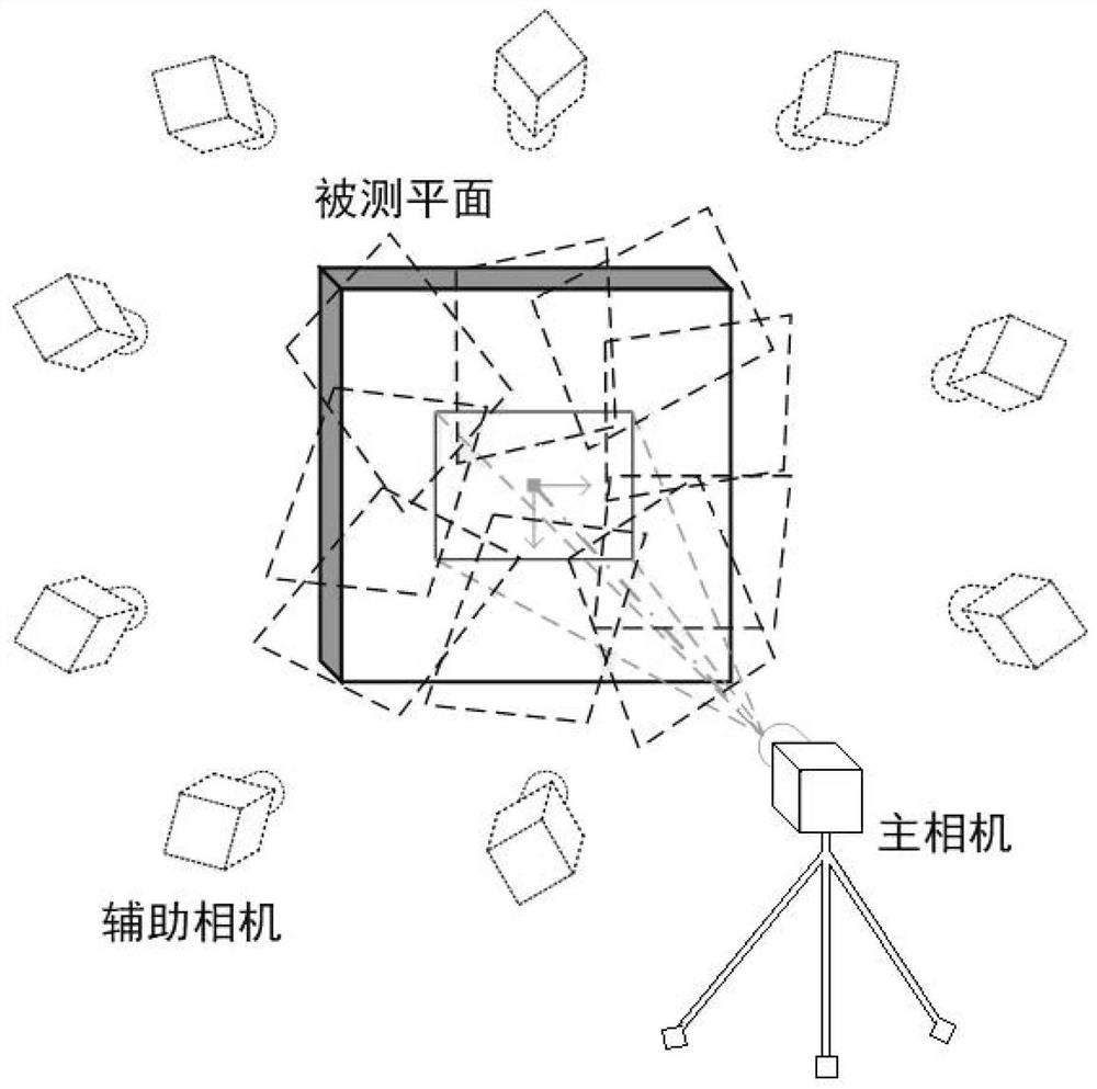
[0037] The present invention needs to use two gray-scale cameras with the same model and lens, which are respectively called the main camera and the auxiliary camera. The main camera is used to capture the central view, and the secondary camera is used to capture supplementary views. The angle of view captured by the camera is shown in 2.

[0038] The first step is to prepare random scattered black and white spots on the surface to be tested. You can use paint spraying, marking pens or paint to ensure that the black and white spots on the tested surface can be firmly attached to the tested surface and follow the surface deformation;

[0039] The second step is to use a tripod to place the auxiliary camera so that the auxiliary camera faces the central area of ​​the surface to be measured, fix the position of the tripod, fix the focal length afte...


PUM


Abstract

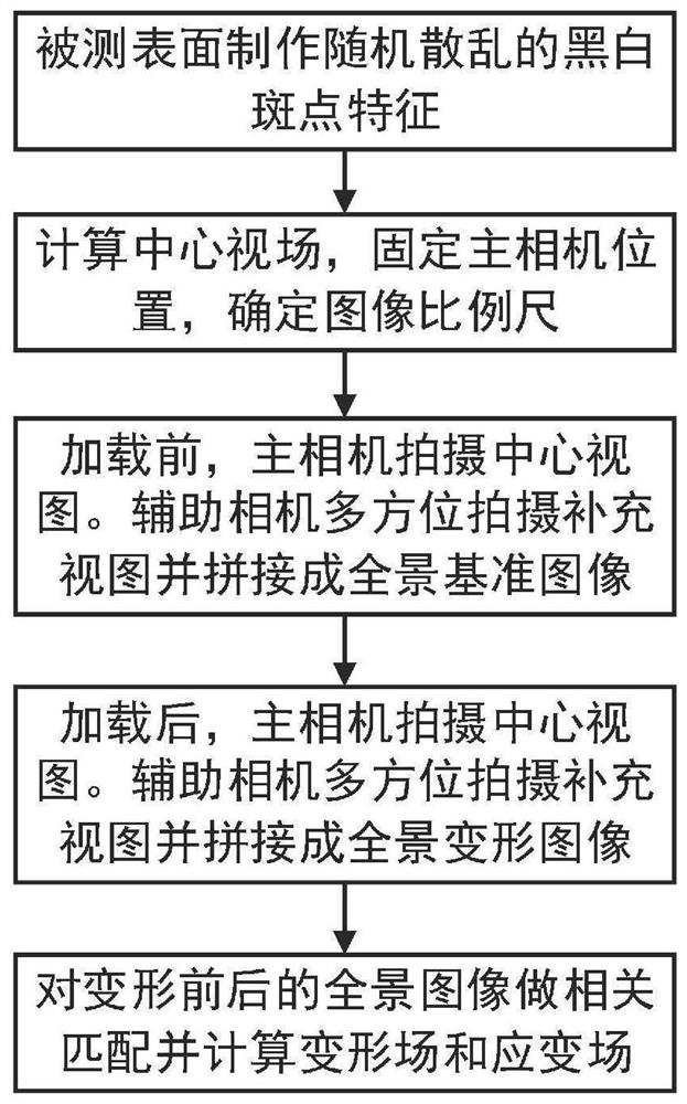
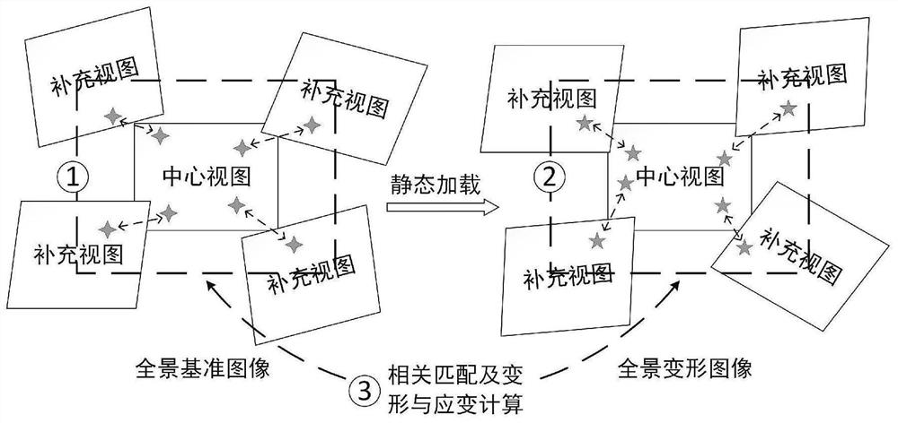
The invention discloses a method for measuring quasi-static stress deformation in a large-view-field plane. The method comprises the following steps that: (1) randomly scattered black and white spot features are prepared for a measured surface; (2) a main camera is fixed to shoot a picture of the center of a measurement area to serve as a center view, and the proportional relation between image pixels and the actual view field size is determined; (3) before loading, an auxiliary camera shoots a picture around the center view as a supplementary view, and the pictures are spliced to form a panoramic reference image; (4) after loading, the main camera takes a picture as a deformed center view, the auxiliary camera takes a picture around the center view as a deformed supplementary view, and the pictures are spliced to form a panoramic deformed image; and (5) a deformation field and a strain field are calculated for the two panoramic images by using a digital image correlation method. According to the measurement method, camera calibration is not needed, measurement of large-view-field plane deformation is simple and convenient, and full-field measurement of a large-size plane is achieved.

Description

technical field [0001] The invention belongs to the technical field of measurement of experimental mechanics, and in particular relates to a measurement method for quasi-static force deformation in a large field of view plane. An easy-to-implement method for obtaining two-dimensional deformation fields and strain fields of large-scale planes under static or quasi-static forces. Background technique [0002] The force deformation on the surface of an object under a large field of view has great measurement requirements. Such as coal mine loading test, wall bridge deck force deformation test, explosion impact wall test, earthquake simulation test, etc. At present, for this situation, commonly used visual measurement methods include photogrammetry technology and three-dimensional digital image correlation method. The former sticks marker points on the measured object, and after the load is stable, takes multiple images of the measured surface to reconstruct the spatial coordi...

Claims


Application Information

Patent Timeline
Patent Type & Authority Applications(China)
IPC IPC(8): G01B11/16G06T7/00G06T7/33G06T7/62G06T3/40G06K9/62
CPCG01B11/16G06T7/0002G06T7/33G06T7/62G06T3/4038G06T2200/32G06T2207/10004G06F18/22Y02T90/00
Inventor 千勃兴邵伟华灯鑫高瑞鹏王晛
Owner XIAN UNIV OF TECH
Learn More