Toughness detection device for cable processing

A detection device and cable technology, which is applied to measurement devices and uses a stable bending force to test the strength and strength characteristics of materials, can solve the problems of poor applicability, inconvenient use, bloated mechanism, etc., and achieve high bending efficiency and convenient use. , the effect of strong applicability

Pending Publication Date: 2021-06-15
安徽鸿运仪表线缆股份有限公司
View PDF0 Cites 1 Cited by
  • Summary
  • Abstract
  • Description
  • Claims
  • Application Information

AI Technical Summary

Problems solved by technology

[0004] The purpose of the present invention is to solve the problems of bloated mechanism, inconvenient use and poor applicability in the prior art, and propose a toughness detection device for cable processing

Method used


Image

  • Toughness detection device for cable processing
  • Toughness detection device for cable processing
  • Toughness detection device for cable processing

Examples


Embodiment 1

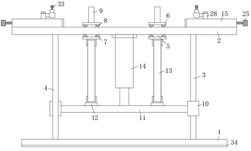
[0027] Refer Figure 1-4 A toughness detecting device for cable processing, including the base 1, and the bottom of the base 1 is provided with a detection table 2, and the bottom portion of the detecting table 2 is fixed to the base 1, and there is a track penetrating rod 3, or the track penetration rod 3 has two For the detecting table 2, there is a track long hole, and there are two orbital long holes and each other, and the track is slidably connected to the slider 5, and both ends of the slider 5 extend to the detection table 2. On the side and fixing the top side of the top plate 6 and the bottom plate 7, the top side of the top plate 6 is fixedly connected with two positioning rod 9, and the outer sliding sleeve of the rod portion of the track pendulum 3 is provided with a slider 10, and the two slider 10 is fixedly connected. There is a horizontal plate 11, and the top side of the cross plate 11 is fixedly connected to the connecting plate 12, and the connecting plate 12 is...

Embodiment 2

[0030] Such as Figure 1-4 As shown, the present embodiment is substantially identical, preferably, the base 1 and the detection table 2 are fixedly connected to the auxiliary support rod 4, and the auxiliary support rod 4 has two, two auxiliary support rods 4 and two tracks. The vertical rod 3 is a rectangular cross-distribution.

[0031] In this embodiment, the arrangement of the auxiliary support rod 4 is supported by the track penetration rod 3, so that the state of the detecting table 2 is more stable.

Embodiment 3

[0033] Such as Figure 1-4 As shown, the present embodiment is substantially the same as that, preferably, the top plate 6 and the bottom plate 7 are mounted on one side of the detection table 2, and the minus beads 8 are located on both sides of the orbital longifuane. On the side of the minus bead 8, the side of the detection table 2 scrolls the contact connection.

[0034] In the present embodiment, the arrangement of the devil bead 8 causes the slider 5, the top plate 6, and the bottom plate 7 more smoothly in the horizontal reciprocating movement, and reduces friction loss.


PUM


Abstract

The invention discloses a toughness detection device for cable processing. The toughness detection device comprises a base, a detection table is arranged vertically above the base, and two track vertical rods are fixedly connected between the bottom of the detection table and the base. The table body of the detection table is provided with two long track holes, and the long track holes are arranged in parallel. Sliding rods are slidably connected in the long track holes, the two ends of the sliding rods extend to the two sides of the detection table respectively and are fixedly connected with a top plate and a bottom plate, and the top side of the top plate is fixedly connected with two positioning vertical rods. The outer sides of rod bodies of the track vertical rods are slidably sleeved with sliding cylinders, a transverse plate is fixedly connected between the two sliding cylinders, and the top side of the transverse plate is fixedly connected with two connecting plates. According to the invention, the cable detection accuracy is ensured, the structure is simple, the design is reasonable, the use is convenient, the applicability is high, and the use requirements of people in production and life are met.

Description

Technical field [0001] The present invention relates to the field of cable detection, and more particularly to a toughness detecting device for cable machining. Background technique [0002] Cable is a power or signal transmission device, which is usually composed of several or several sets of wires, cables, control cables, compensation cables, shielded cables, high temperature cables, computer cables, signal cables, coaxial cables, fire resistance cables , Boat cable, mine cable, aluminum alloy cable, etc. They are composed of single or multi-strand wires and insulating layers, used to connect circuits, electrical appliances, etc. [0003] With the development of society and technology, the frequency of use of cables is getting bigger and larger, and the types of cables are increasing. In the process of cable production, the detection of cables is also very important, and the toughness of the cable. It is important that the guarantees of the subsequent use of the cable are very ...

Claims


Application Information

Patent Timeline
Patent Type & Authority Applications(China)
IPC IPC(8): G01N3/20G01N3/04
CPCG01N3/04G01N3/20G01N2203/0023
Inventor 陈林霞王康乐
Owner 安徽鸿运仪表线缆股份有限公司
Why Eureka
Try Eureka