Gas condensation visualization and heat exchange characteristic detection device and method

A detection device, gas condensation technology, applied in the direction of measuring devices, material condensation, material thermal development, etc., can solve problems such as inaccurate flow control, thermocouple corrosion, equipment failure, etc., to enhance protection performance, ensure reliable and accurate work, Increases the effect of protection time

Active Publication Date: 2021-06-15
UNIV OF SCI & TECH BEIJING
View PDF32 Cites 2 Cited by
  • Summary
  • Abstract
  • Description
  • Claims
  • Application Information

AI Technical Summary

Problems solved by technology

In addition, in the actual application process, many gases to be condensed have relatively high boiling points, such as NO 2 , VOC, etc. Condensation often occurs at the pipeline and flowmeter during the gas distribution process, resulting in inaccurate flow control and equipment failure, and it is difficult for the flowmeter to be directly heated, but there are no relevant solutions in the existing patents
What is more difficult is that some corrosive gases will cause irreversible corrosion and damage to thermocouples when they condense. In order to measure temperature accurately and quickly, armored thermocouples cannot be used. It is a must to protect and seal thermocouples in small devices. tricky question

Method used


Image

  • Gas condensation visualization and heat exchange characteristic detection device and method
  • Gas condensation visualization and heat exchange characteristic detection device and method
  • Gas condensation visualization and heat exchange characteristic detection device and method

Examples


Embodiment 1

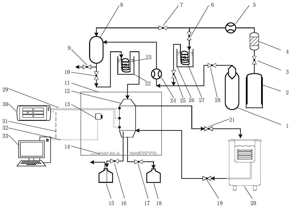
[0074] refer to figure 1 , this embodiment proposes a visual detection device for gas condensation heat transfer characteristics, the visual detection device includes:

[0075] Gas distribution unit, condensing unit, refrigeration unit and data acquisition unit;

[0076] The gas distribution unit is connected to the condensing unit, the refrigerating unit provides cooling capacity for the condensing unit, and the data acquisition unit collects temperature information and image information of the condensing unit.

[0077] refer to figure 1 , in this embodiment, the gas distribution unit includes:

[0078] Gas cylinder to be condensed 1, first rotameter 5, non-condensable gas cylinder 2, molecular sieve dehydration adsorber 4, second rotameter 24, gas mixing tank 8, heating system, constant temperature system and several first valves A ~G;

[0079] The non-condensable gas cylinder 2, the molecular sieve dehydration adsorber 4, the first rotameter 5 and the gas mixing tank 8 ...

Embodiment 2

[0108] This embodiment proposes a detection method using the visual detection device for gas condensation heat transfer characteristics described in Embodiment 1; the detection method includes the following steps:

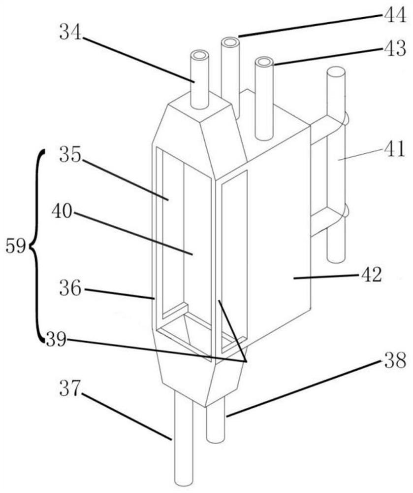
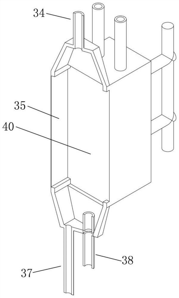
[0109] S1, install the thermocouple: install the thermocouple on the condensing device 12, the installation position includes: the gas inlet and outlet of the condensing device, the gas space in the airflow channel, and the condensing wall of the condensing device; the condensing wall of the condensing device is the same as the low-temperature water tank 42 the contact surface;

[0110] S2, refrigerating: using a refrigerator 20 to refrigerate the condensing device 12;

[0111] Specifically: open the refrigerator 20, the third valve A19 and the third valve A21, so that the brine circulates between the refrigerator 20 and the condensing device 12, and continuously transfers the cooling capacity to the condensing device 12;

[0112] S3, heating the second rotameter ...

Embodiment 3

[0127] According to the detection method of above-mentioned embodiment 2, this example uses high boiling point gas NO 2 As the gas to be condensed, the following detection tests are carried out with air as the non-condensable gas:

[0128] In this experiment, the air is only used to heat the second rotameter 24 and does not interact with the NO 2 The mixture enters the condensing unit 12.

[0129] The refrigerator was set at -10°C to -30°C to study NO 2 Condensation of mixed gas on 316 metal wall. Gas to be condensed NO 2 Cylinders are heated to 45°C to ensure NO 2 The gas flows out of the gas cylinder continuously, and the pipeline and gas mixing tank are heated to 60-70°C to prevent NO 2 Condensate before entering the condensing unit. Air heats the second rotameter 24, closes the non-condensable gas cylinder 2 after heating; then adjusts the second rotameter 24 to carry out 200ml / min of pure NO 2 Condensation of gas at -10°C, -15°C, -17°C, -19°C, -20°C, -21°C, -23°C, ...


PUM


Abstract

The invention belongs to the technical field of gas condensation, and particularly relates to a visual detection device and method for gas condensation heat exchange characteristics. The visual detection device comprises a gas distribution unit, a condensation unit, a refrigeration unit and a data acquisition unit, wherein the gas distribution unit is connected with the condensation unit, the refrigeration unit provides cooling capacity for the condensation unit, and the data acquisition unit acquires temperature information and image information of the condensation unit. The visual detection device captures condensation mode pictures and videos and meanwhile achieves collection of temperature and liquid amount data so as to achieve calculation of the heat exchange coefficient. Undue condensation of the high-boiling-point gas at the flow control position can be effectively prevented, and the condensation process of the gas can be deeply understood through videos and picture data shot at multiple angles on the front face and the side face and heat exchange coefficient changes correspondingly obtained in real time; the side rotary high-frequency switching light source can realize multi-angle adjustable light quantity supply to meet the light source requirement of the image capture equipment.

Description

technical field [0001] The invention belongs to the technical field of gas condensation, and in particular relates to a visual detection device and detection method for gas condensation heat transfer characteristics. Background technique [0002] The condensation process is a phenomenon that is often seen in nature, life, and industrial processes. It is mainly divided into drop condensation, film condensation, and fog condensation. For different gases (pure gas or non-condensable gas) and wall properties (hydrophobic strength, shape, etc.), the specific condensation mode is often more complicated, and the current research method is mainly based on speculation. , simulations and experimentally based hypotheses, droplet condensation started and developed. Condensation visualization experiments and the change law of condensation heat transfer coefficient are helpful to better grasp the condensation process and mechanism in specific problems, capture the evolution law of conden...

Claims


Application Information

Patent Timeline
Patent Type & Authority Applications(China)
IPC IPC(8): G01N25/14G01N25/20
CPCG01N25/142G01N25/20
Inventor 李子宜刘应书孙宁起刘佳欣杨雄刘文海刘志伟
Owner UNIV OF SCI & TECH BEIJING
Why Eureka
Try Eureka