Testing device and testing method for water cooling system of rail transit converter

A water-cooling system and rail transit technology, applied in the cooling field of rail transit vehicles, can solve the problems of difficult layout of measuring points, large test equipment, and small internal space, so as to facilitate the operation of data collection on the test site, increase the test space, The effect of reducing the size of the device

Pending Publication Date: 2021-06-15
CHINA ACADEMY OF RAILWAY SCI CORP LTD +3
View PDF0 Cites 3 Cited by
  • Summary
  • Abstract
  • Description
  • Claims
  • Application Information

AI Technical Summary

Problems solved by technology

[0003] First, the entire test device is huge and the test method is complicated; at present, the power unit converter tends to be miniaturized gradually, with a high degree of integration and a small internal space, so it is difficult to arrange corresponding measuring points and conduct relevant test research; The test data of the current converter water cooling system only include the air flow rate at the inlet of the cooling device and the water temperature at the inlet and outlet of the cooling device, so parameters such as air heat absorption and water heat dissipation can only be roughly calculated
[0004] Second, the air-cooling system and the water-cooling system in the entire power unit converter will work at the same time. When the complete power unit converter is used for the test, the measured test data is the data under the joint cooling of the air-cooling system and the water-cooling system , and the cooling water pipe will also pass through components that do not need water cooling during water cooling, which makes the final measured data not the data under the pure action of the water cooling system, and cannot accurately measure the quantitative effect of the water cooling system on the cooled device alone. data
Therefore, the existing converter water-cooling system tests are not able to study the properties of the water-cooling system in depth

Method used


Image

  • Testing device and testing method for water cooling system of rail transit converter
  • Testing device and testing method for water cooling system of rail transit converter
  • Testing device and testing method for water cooling system of rail transit converter

Examples


Embodiment Construction

[0057] In order to understand the technical features, objects, and effects of the present invention, specific embodiments of the present invention will be described with reference to the drawings.

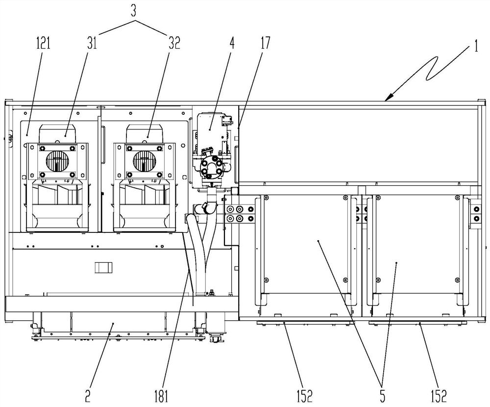
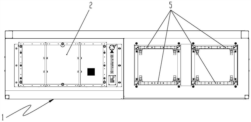
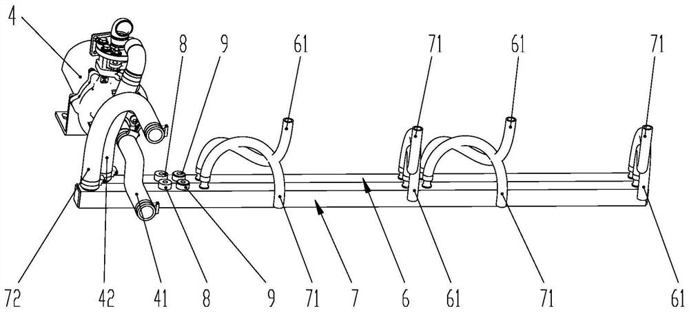
[0058] Such as Figure 1 to 6 As shown, the present embodiment provides a rail transformer water cooling system test device including a test chamber 1 in a rectangular body shape. An intermediate spacer 17 is provided along the width direction in the test chamber 1 to separate the test chamber 1 into each other and close to the first end and the second end of the test chamber 1, respectively, and the birting chamber 18. At the first side of the test chamber 1 and the position of the corresponding dirty chamber 18, there is a total inlet air outlet 151, and in the dirty chamber 18, a windshield 181 with through holes 1811 is provided, and the windshield 181 is separated. The guide cavity 182 communicates with the total air inlet 151 and the mounting chamber 183 near the second side of th...


PUM


Abstract

The invention relates to a rail transit converter water cooling system test device and test method. The rail transit converter water cooling system test device comprises a test box, wherein a middle partition plate is arranged in the test box to divide the test box into a dirty chamber and a clean chamber which are mutually independent and respectively close to a first end and a second end of the test box; a main air inlet is formed in the first side of the test box, a wind shield with a through hole is arranged in the dirty chamber, and the wind shield divides the dirty chamber into a wind guide cavity communicated with the main air inlet and a mounting cavity close to the second side of the test box; a radiator is fixedly arranged outside the first side of the test box, and a fan and a water pump are arranged in the mounting cavity; a plurality of water cooling plates are arranged in the clean chamber, and each water cooling plate is provided with a heating part. The device is small in size, convenient to install and easy to operate, can be used for testing data under the independent action of the water cooling system, and is more convenient for deeply researching attributes of the water cooling system.

Description

Technical field [0001] The present invention relates to the field of cooling techniques of rail transit vehicles, and more particularly to a test device and test method of rail transformer water cooling system. Background technique [0002] The power unit converter is an important massive electrical component on the high-speed train group, which integrates all functions of traction converters, auxiliary converters, and cooling units in their box. Among them, the traction converter mainly includes a traction control unit, a power module, a contactor, a resonant capacitor, and the auxiliary converter mainly includes auxiliary transformer, a resonant reactor, and the like, and the cooling unit includes a fan, a heat sink, a water pump, a cooling water pipe, and the like. The air-cooled transformer in the cooling unit can be air cooling on the radiator and the auxiliary transformer in the auxiliary converter, and the power module in the traction converter can be water-cooled by using...

Claims


Application Information

Patent Timeline
Patent Type & Authority Applications(China)
IPC IPC(8): G01N25/20G01M99/00G01D21/02
CPCG01D21/02G01M99/002G01N25/20
Inventor 刘直刘秀川杨伟君宫帅朱雨桐刘阳左鹏张若冰郑海源赵洪利
Owner CHINA ACADEMY OF RAILWAY SCI CORP LTD
Why Eureka
Try Eureka