Radial polarizer for particle detection

A polarizer and detector technology, applied in instruments, measuring devices, scientific instruments, etc., can solve problems such as inability to achieve sensitive image quality

Active Publication Date: 2021-06-15
KLA TENCOR CORP
View PDF12 Cites 0 Cited by
  • Summary
  • Abstract
  • Description
  • Claims
  • Application Information

AI Technical Summary

Problems solved by technology

While various approaches have been proposed to suppress surface scatter relative to scatter from particles, such approach

Method used


Image

  • Radial polarizer for particle detection
  • Radial polarizer for particle detection
  • Radial polarizer for particle detection

Examples


Embodiment Construction

[0025] Reference will now be made in detail to the disclosed subject matter illustrated in the accompanying drawings. The invention has been particularly shown and described with respect to particular embodiments and its particular features. The embodiments set forth herein are to be regarded as illustrative and not restrictive. As used herein, directional terms (e.g., "left," "right," "top," "bottom," "above," "below," "up," "upward," "down," "downward") and "downward") are intended to provide relative positions for descriptive purposes, and do not wish to specify an absolute frame of reference. It will be readily apparent to those skilled in the art that various changes and modifications in form and details can be made without departing from the spirit and scope of the invention.

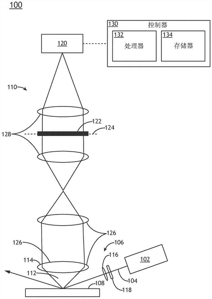
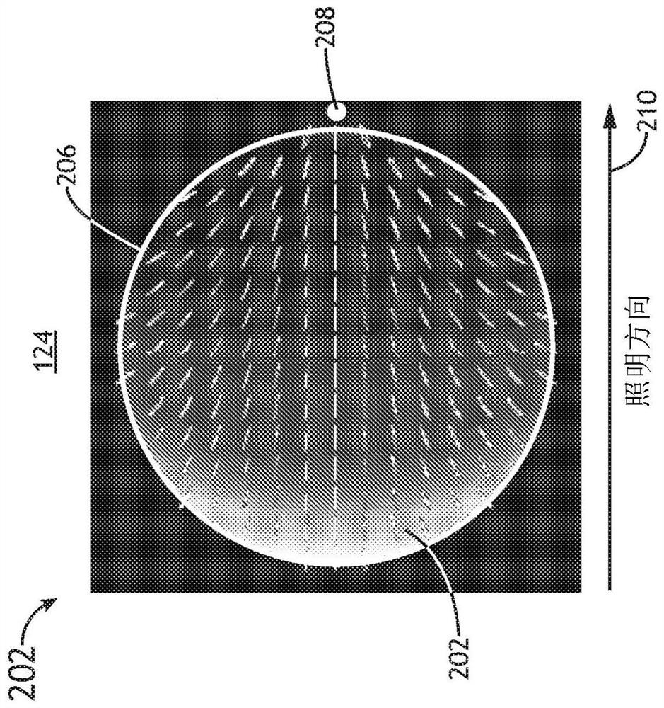
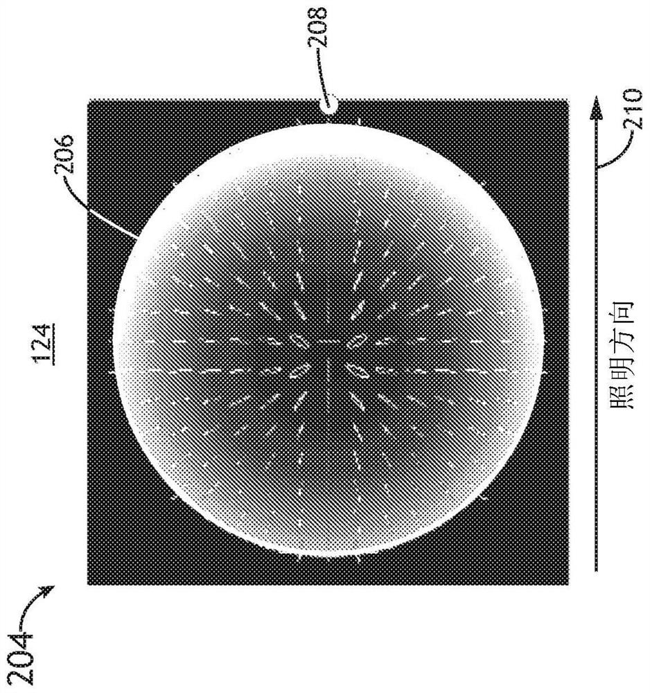
[0026] Embodiments of the invention relate to dark field imaging for selective filtering of surface scatter (e.g., surface haze) based on utilizing a haze-repelling polarizer in the pupil plane ...


PUM


Abstract

A dark field inspection system may include an illumination source to generate an illumination beam; one or more illumination optics to direct the illumination beam to a sample at an off-axis angle along an illumination direction; a detector; one or more collection optics to generate a dark-field image of the sample on the detector based on light collected from the sample in response to the illumination beam; and a radial polarizer located at a pupil plane of the one or more collection optics, where the radial polarizer rejects light with radial polarization with respect to a reference point in the pupil plane corresponding to specular reflection of the illumination beam from the sample.

Description

[0001] Cross References to Related Applications [0002] This application asserts under 35 U.S.C. §119(e) that Jenn-Kuen Leong, Daniel Kavaldjiev, John Fielden, and Guoheng Zhao) U.S. Provisional Application Serial No. 62 / 767,246 entitled "PARTICLE DETECTION WITH IMPROVED RESOLUTION ON WAFER INSPECTION SYSTEM" filed on November 14, 2018 interest in the case, which is incorporated herein by reference in its entirety. technical field [0003] The present invention relates generally to particle inspection, and more particularly to dark field particle inspection. Background technique [0004] Particle inspection systems are commonly used in semiconductor processing lines to identify defects or particles on wafers such as, but not limited to, unpatterned wafers. As semiconductor devices continue to shrink, particle detection systems require a corresponding increase in sensitivity and resolution. A significant source of noise that can limit measurement sensitivity is surface s...

Claims


Application Information

Patent Timeline
IPC IPC(8): G01N21/94G01N21/47G01N15/02G01N21/84
CPCG01N21/8806G01N21/94G01N21/9501H01L22/12H01L22/10G01N2021/8822G01N2021/8848G01N21/47G01N15/0211G01N2021/473G01N2021/8461G01N21/21G01N21/95607
Inventor J-K·龙D·卡瓦德杰夫国衡·赵
Owner KLA TENCOR CORP
Why Eureka
Try Eureka