Hydraulic plate shearing machine

A technology of hydraulic shears and triggers, which is applied in the direction of shearing devices, shearing machine equipment, and accessories of shearing machines, etc. It can solve the problems of lack of limit guides for thin steel plates, time-consuming and labor-intensive manual cutting, and irregular shapes of thin steel plates. problem, to avoid manual cutting time-consuming and laborious, to improve the shearing rate, and to achieve the effect of consistent size

Inactive Publication Date: 2021-06-18
彭威海
View PDF0 Cites 3 Cited by
  • Summary
  • Abstract
  • Description
  • Claims
  • Application Information

AI Technical Summary

Problems solved by technology

[0004] (1) When the rolled thin steel plate is cut by manual cutting, usually the unrolled thin steel plate is directly cut manually, and then the cut thin steel plate is manually collected and stacked, and the manual cutting It is time-consuming and labor-intensive, and it is difficult to ensure that the cut thin steel plates are of the same size during the cutting process;
[0005] (2) When the existing hydraulic shearing machine cuts the thin steel plate, it usually cuts the thin steel plate by intermittent feed cutting, which makes the cutting efficiency of the thin steel plate low, and the existing hydraulic During the cutting process of the shearing machine, there is no limit guide for the thin steel plate when moving and feeding, so that the thin steel plate is shifted when feeding, which leads to irregular shape of the thin steel plate after cutting

Method used


Image

  • Hydraulic plate shearing machine
  • Hydraulic plate shearing machine
  • Hydraulic plate shearing machine

Examples


Embodiment Construction

[0037] In order to make the technical means realized by the present invention, creative features, goals and effects easy to understand, the following combination Figure 1 to Figure 10 , to further elaborate the present invention.

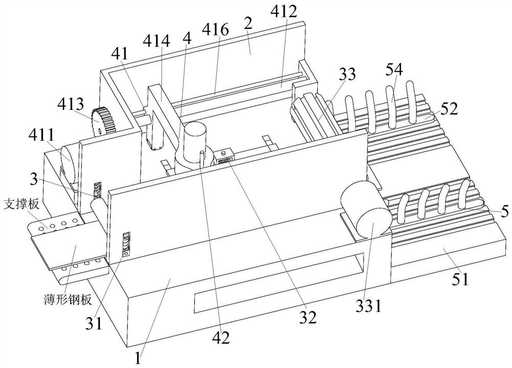
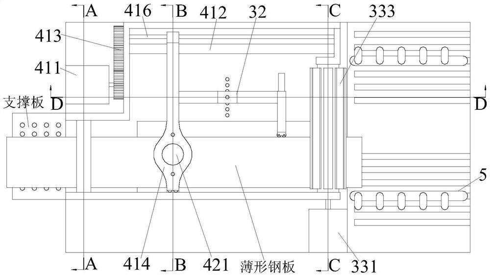
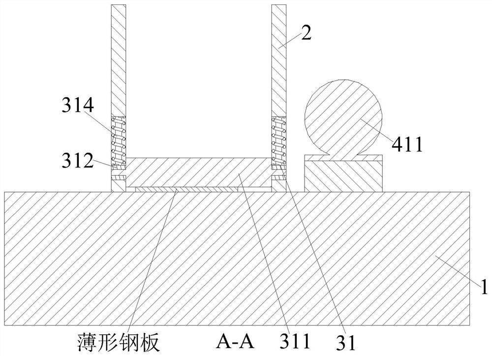
[0038] A hydraulic shearing machine, comprising a base plate 1, a side plate 2, a feeding device 3, a cutting device 4 and a stacking device 5, the side plate 2 is installed in the middle of the upper end of the base plate 1, and the feeding device 3 is installed at the upper end of the base plate 1 , a cutting device 4 is arranged above the upper road Austrian device, and the cutting device 4 is installed on the inner side of the side plate 2 located on the rear side, and a stacking device 5 is installed on the right end of the bottom plate 1; wherein:

[0039] The feeding device 3 includes a flattening mechanism 31, a pressing mechanism 32 and a traction mechanism 33. The left side of the side plate 2 is equipped with a flattening mechanism 31, a...


PUM

PropertyMeasurementUnit
thicknessaaaaaaaaaa

Abstract

The invention relates to a hydraulic plate shearing machine. Cutting work of thin steel plates is completed through cooperation of a bottom plate, side plates, a feeding device, a cutting device and a stacking device. The hydraulic plate shearing machine can solve the problems that during manual shearing, because unreeled thin steel plates are directly sheared firstly, and then the sheared thin steel plates are manually collected and stacked, manual shearing wastes time and labor, and in the shearing process, it is difficult to guarantee that the sizes of the sheared thin steel plates are consistent, and when an existing hydraulic plate shearing machine shears the thin steel plates, because an intermittent feeding and shearing mode is usually adopted for shearing the thin steel plates, the shearing efficiency of the thin steel plates is low due to intermittent feeding and shearing, and because the existing hydraulic plate shearing machine does not limit and guide the thin steel plates in the movable feeding process during shearing, the thin steel plate deviates in the feeding process, and then the shapes of the thin steel plates are irregular after the thin steel plates are sheared.

Description

technical field [0001] The invention relates to the technical field of plate cutting, in particular to a hydraulic shearing machine. Background technique [0002] Thin steel plate is a steel plate with a thickness between 0.2 and 4mm produced by hot rolling or cold rolling. The width of the thin steel plate is between 500mm and 2500mm. According to different uses, thin steel plates have different materials: ordinary carbon steel, high-quality carbon structural steel, alloy structural steel, carbon tool steel, stainless steel, spring steel, silicon steel for electrical purposes, etc. Mainly used in automobile industry, aviation industry, enamel industry, electrical industry, machinery industry and other departments. Thin steel plates are used directly after rolling, as well as those that have been pickled (pickling thin steel plates) and galvanized or tinned. After forming, thin steel plates are usually rolled up for easy storage. It needs to be unrolled and cut to use. ...

Claims


Application Information

Patent Timeline
Patent Type & Authority Applications(China)
IPC IPC(8): B23D15/06B23D15/14B23D33/00B21D1/02
CPCB21D1/02B23D15/06B23D15/14B23D33/00
Inventor 彭威海李萍
Owner 彭威海
Why Eureka
Try Eureka