Motor train unit profile cavity welding deformation control device and control method

A control device, welding deformation technology, applied in welding equipment, welding equipment, auxiliary equipment, etc., can solve problems affecting product appearance, welding quality and production efficiency, difficult to restore the original shape, difficult to repair, etc., to achieve a novel and reliable structure , Reduce the number of repairs, improve the effect of weld size

Active Publication Date: 2021-06-18
CRRC CHANGCHUN RAILWAY VEHICLES CO LTD
View PDF23 Cites 0 Cited by
  • Summary
  • Abstract
  • Description
  • Claims
  • Application Information

AI Technical Summary

Problems solved by technology

[0003] In the prior art, all EMUs use aluminum alloy profile structures. In order to meet the lightweight structure design of the car body and thinner profile wall thickness, it is easy to deform around the machined opening cavity during the welding process of aluminum alloy profiles. It is more difficult, and it is difficult to restore the original shape after repairing, which affects product appearance, welding quality and production efficiency
[0004] However, there is no device in the prior art that can control welding deformation during the welding process of aluminum alloy profiles. Therefore, based on the above technical problems, it is urgent for those skilled in the art to develop a control method for controlling the welding deformation of EMU profile cavities. Device and control method for controlling profile cavity welding deformation based on the control device

Method used


Image

  • Motor train unit profile cavity welding deformation control device and control method
  • Motor train unit profile cavity welding deformation control device and control method
  • Motor train unit profile cavity welding deformation control device and control method

Examples


Embodiment Construction

[0057] In order to enable those skilled in the art to better understand the technical solutions of the present invention, the present invention will be further described in detail below in conjunction with the accompanying drawings.

[0058] see Figure 1 to Figure 7 shown;

[0059] A control device for welding deformation of a profile cavity of an EMU according to the present invention, the control device includes:

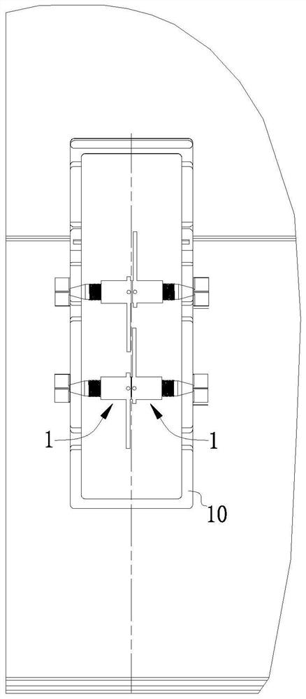
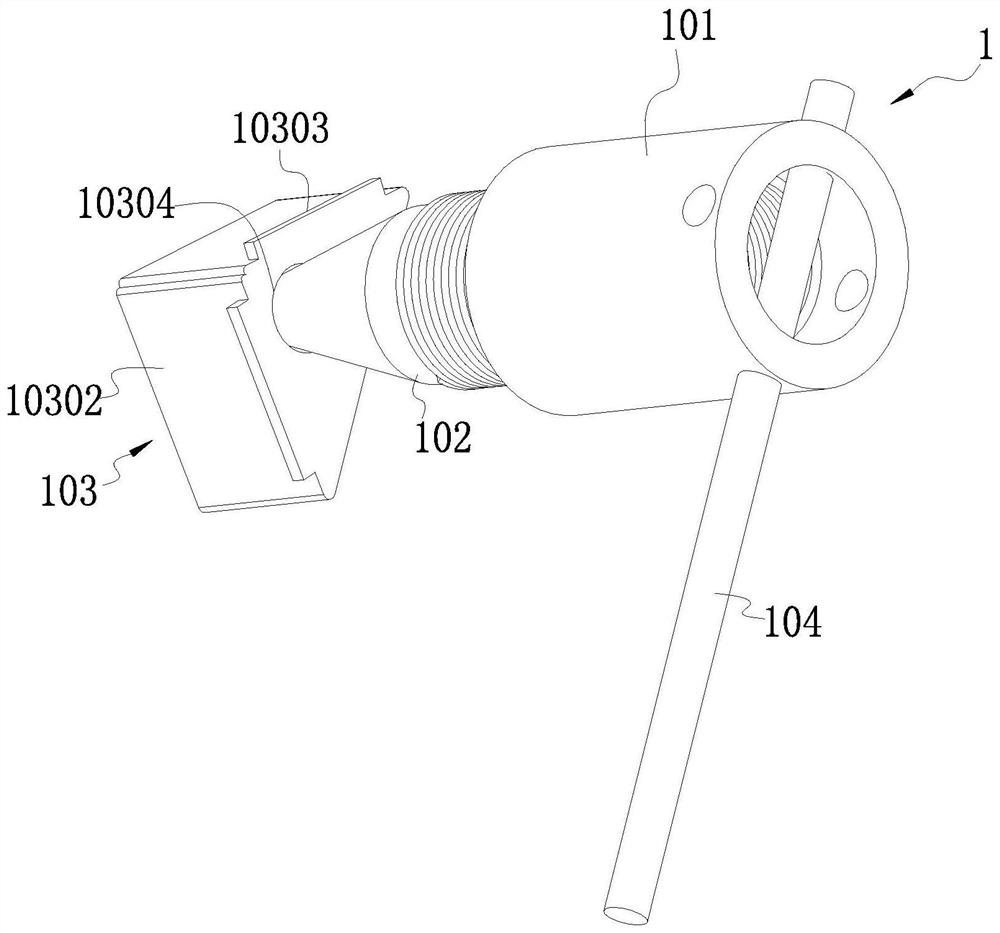
[0060] Two groups of cavity control mechanisms 1;

[0061] One end of the cavity control mechanism 1 is configured as an operating end, and the other end of the cavity control mechanism 1 is configured as a cavity support end;

[0062] The operating ends of the two groups of cavity control mechanisms 1 are in contact with each other, and the cavity support ends of the two groups of cavity control mechanisms 1 extend toward the outside;

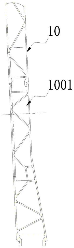
[0063] The cavity supporting end of the cavity control mechanism 1 is embedded in the cavity 1001 of the profile 10;

[006...


PUM


Abstract

The invention discloses a motor train unit profile cavity welding deformation control device and a control method. The motor train unit profile cavity welding deformation control device comprises two sets of cavity control mechanisms, one end of each cavity control mechanism is configured as an operation end, and the other end of each cavity control mechanism is configured as a cavity supporting end; the operation ends of the two sets of cavity control mechanisms make contact with each other, and the cavity supporting ends are embedded into a cavity of a profile; and the cavity supporting ends keep the relative position with the inner wall of the cavity of the profile through a transmission structure. According to the control device, the expansion degree of an expansion block is controlled through a rotary cone so as to change the degree of supporting to the cavity of the profile, it is guaranteed that no large deformation occurs in the welding process through supporting of the expansion block, and therefore the appearance quality of the profile after welding is guaranteed; the device is convenient to operate and novel and reliable in structure, compared with a traditional means, more time and labor are saved during machine or flame adjusting and repairing, the adjusting and repairing frequency is reduced due to one-time welding forming, and the size, quality and structural strength of a welding seam can be effectively improved.

Description

technical field [0001] The invention relates to the technical field of EMU profile processing, in particular to a control device for controlling the welding deformation of the profile cavity of the EMU and a control method for controlling the welding deformation of the profile cavity based on the control device. Background technique [0002] The aluminum alloy car body structure is an aluminum profile structure with a cavity. Due to the large amount of aluminum alloy welding deformation, the requirements for the surface flatness and radian of the car body structure are relatively high, especially around the profile processing openings, which are affected by the reduction in strength and are prone to occur. Welding deformation, difficult repairs and repeated repairs will reduce the strength of the weld. It is very important in aluminum alloy welding process to reduce the adjustment process and even avoid adjustment in one-time welding. [0003] In the prior art, all EMUs use...

Claims


Application Information

Patent Timeline
Patent Type & Authority Applications(China)
IPC IPC(8): B23K31/00B23K31/02B23K37/00B23K37/04
CPCB23K31/003B23K31/02B23K37/00B23K37/0443Y02T30/00
Inventor 王永亮范明保刘友蛟
Owner CRRC CHANGCHUN RAILWAY VEHICLES CO LTD
Why Eureka
Try Eureka