
Automatic welding device capable of efficiently replacing filler rods

An automatic welding and electrode technology, applied in auxiliary devices, welding equipment, auxiliary welding equipment, etc., can solve the problems of low degree of automation, reduced welding efficiency, lack of automatic replacement of welding electrodes, etc., so as to reduce the frequency of electrode replacement and improve welding efficiency. , to ensure the effect of welding efficiency

Inactive Publication Date: 2021-06-18
新余山海企业服务有限公司
View PDF0 Cites 3 Cited by
  • Summary
  • Abstract
  • Description
  • Claims
  • Application Information

AI Technical Summary

Problems solved by technology

[0003] As the welding rod continues to melt during the welding process, its length will decrease as the working time increases. Therefore, when moving welding, it is necessary to continuously press down on the feeding material while moving, but the existing automatic welding equipment needs Through manual feeding, the degree of automation is low, and at the same time, it lacks the function of automatically changing the welding rod, so that every time the welding rod is used up, the replacement must be suspended, thereby reducing the overall welding efficiency

Method used


Image

  • Automatic welding device capable of efficiently replacing filler rods
  • Automatic welding device capable of efficiently replacing filler rods
  • Automatic welding device capable of efficiently replacing filler rods

Examples


Embodiment Construction

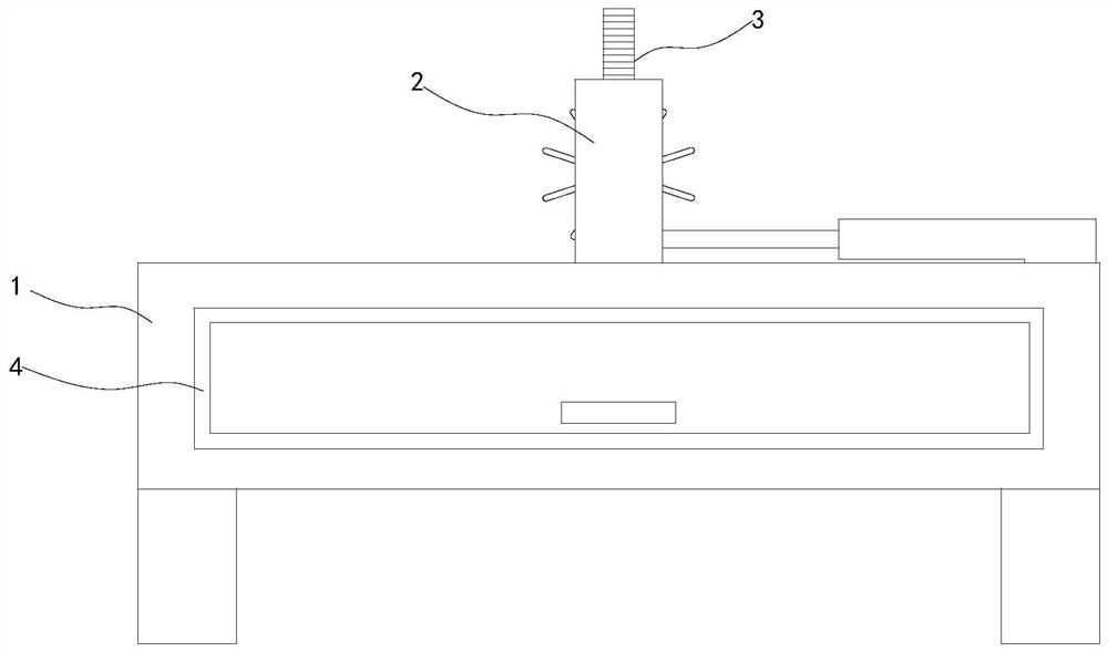
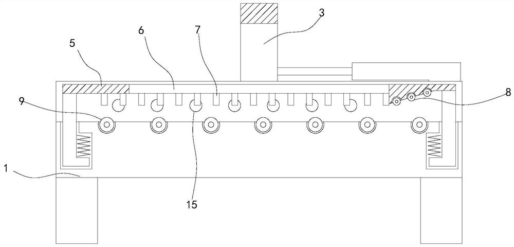
[0033] see Figures 1 to 12 , a schematic plan view and a three-dimensional structure view of an automatic welding device for efficiently replacing electrodes.

[0034] The invention provides an automatic welding device for efficiently replacing welding rods, comprising a device main body 1, a moving frame 2 is movably installed on the upper end of the device main body 1, a welding rod 3 is movably installed on the inner side of the moving frame 2, and an electrode replacement is fixedly installed on the inner side of the moving frame 2 In the device 10 , a fixed plate 5 is movably installed on the upper end of the device main body 1 , and an air injection port 15 is fixedly installed on the side of the device main body 1 opposite to the fixed plate 5 .

[0035] In specific implementation, the right end of the fixed plate 5 is obliquely arranged, and the rotating rod 8 is fixedly installed, the lower end of the moving frame 2 is embedded in the device main body 1, and the weld...


PUM


Abstract

The invention relates to the field of automatic welding, in particular to an automatic welding device capable of efficiently replacing filler rods. The device comprises a device main body, a moving frame is movably mounted at the upper end of the device main body, a welding rod is movably mounted at the inner side of the moving frame, and a filler rod replacing device is fixedly mounted at the inner side of the moving frame; and fixing blocks are fixedly installed in the filler rod replacing device at equal intervals along the edge, standby filler rods can be placed between the fixing blocks, after the filler rods at the lower end of the welding rod are used up, the filler rod replacing device can be driven by a motor to rotate, so that the filler rod replacing device uses a driving plate arranged in an annular wavy manner and located at the left side of the filler rod replacing device, rotation in a driving groove of a propelling block is achieved, when the driving block abuts against the driving plate in an attached manner through a spring at one side of a connecting rod, the propelling block can move left and right along the track of the driving plate, and therefore the standby filler rods at the outer side of the propelling block are pushed into welding tongs at the lower end of the welding rod along with rotation of the filler rod replacing device, and replacement is completed. Therefore, the frequency of filler rod replacement through device pause is greatly reduced.

Description

technical field [0001] The invention relates to the technical field of automatic welding, in particular to an automatic welding device for efficiently replacing welding rods. Background technique [0002] Welding, also known as welding and melting, is a manufacturing process and technology for joining metals or other thermoplastic materials such as plastics by means of heating, high temperature or high pressure, and most of the existing industrial welding processes use automatic welding. In order to save human resources while improving welding efficiency. [0003] As the welding rod continues to melt during the welding process, its length will decrease as the working time increases. Therefore, when moving welding, it is necessary to continuously press down on the feeding material while moving, but the existing automatic welding equipment needs Manual feeding leads to a low degree of automation, and at the same time lacks the function of automatically changing the welding ro...

Claims


Application Information

Patent Timeline
Patent Type & Authority Applications(China)
IPC IPC(8): B23K37/00B23K37/02
CPCB23K37/00B23K37/02
Inventor 韩荣春
Owner 新余山海企业服务有限公司
Learn More