Automatic clamping device used during crystal bar processing

A clamping device and crystal ingot technology, which is applied to fine working devices, stone processing equipment, manufacturing tools, etc., can solve the problems of affecting crystal ingots, increasing production costs, and small contact surfaces, so as to achieve mechanization and reduce Production cost and the effect of improving processing efficiency

Pending Publication Date: 2021-06-18
洛阳市自动化研究所有限公司
View PDF0 Cites 0 Cited by
  • Summary
  • Abstract
  • Description
  • Claims
  • Application Information

AI Technical Summary

Problems solved by technology

[0003] When the above technology is realized, one horizontal crystal rod and two vertical crystal rods are connected by bridging technology, and the two ends of the horizontal crystal rod are drilled, cut or ground into a certain shape, and then ground into a certain shape The grinding surface of the ingot should be lapped corresponding to the groove, or a plug with a certain taper can be set at the end of the ingot to insert into the drilled hole of the ingot to form the final lapping method; however, the aforementioned lapping technology must The horizontal or vertical crystal ingots are processed in advance. According to the current processing capacity, when processing the horizontal or vertical crystal ingots, it is required to keep staff guarding at all times during the processing. When a crystal ingot is processed , in order to prevent safety accidents, the staff must stop the machine first, manually take out the processed ingot, and then install a new ingot, and at the same time, in order to make the ingot grind or drill when grinding or drilling The uniformity of the drilling position requires the staff to continuously adjust the ingot. After the adjustment, restart the equipment for reprocessing. Because this method is subject to a lot of human interference, and when replacing the ingot, it is necessary to Shut down to pick and place the ingot and adjust the position of the ingot, which will inevitably greatly reduce the efficiency of processing and increase the cost of production; it is not conducive to the realization of energy saving and environmental protection, etc., because this method is subject to a very large factor of human interference; for example, The proficiency of the craftsman and the processing conditions of the equipment used may make the holes or grinding grooves on the processed horizontal or vertical crystal rods very irregular, making the contact surface in the later lap bonding process very small, that is, Point contact or line contact, which affects the processing quality of the ingot, etc.

Method used


Image

  • Automatic clamping device used during crystal bar processing
  • Automatic clamping device used during crystal bar processing
  • Automatic clamping device used during crystal bar processing

Examples


Embodiment Construction

[0023] The present invention can be explained in more detail with reference to the following examples, but the present invention is not limited to the combination of these examples.

[0024] First of all, it should be noted that the terms "upper", "lower", "front", "rear", "left", "right", "top", "bottom", "inside", etc. The orientation or positional relationship indicated by "outside" is based on the orientation or positional relationship shown in the drawings, and is only for the convenience of description and simplification of description, rather than indicating or implying that the device or element referred to must have a specific orientation, use a specific configuration and operation, and therefore should not be construed as limiting the invention.

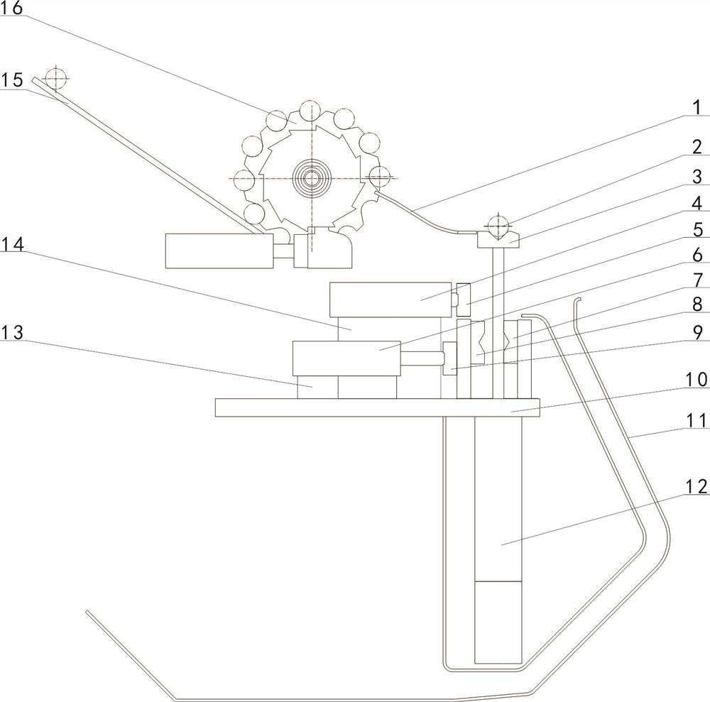
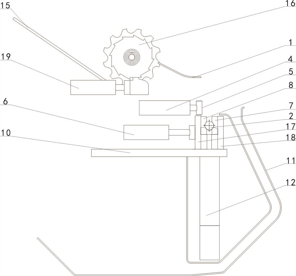
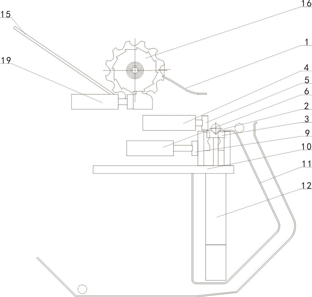
[0025] combined with Figure 1~4 The described automatic clamping device for crystal ingot processing includes a crystal ingot clamping mechanism, a crystal ingot support seat 3, a crystal ingot pusher 4, a bottom plate 10...


PUM


Abstract

The invention relates to auxiliary crystal processing equipment, in particular to an automatic clamping device used during crystal bar processing. According to the automatic clamping device used during crystal bar processing, a crystal bar (2) is driven by a lifter (12) to ascend and descend to achieve operation of the crystal bar at three stations, and the crystal bar is taken, clamped and placed through cooperative action of a crystal bar pusher (4) and a crystal bar clamp (6). The defect that workers stare at points on site for a long term in processing processes is overcome, meanwhile, the processing efficiency is effectively improved, the production cost is reduced, and the like, the automatic clamping device used during crystal bar processing has the advantages of a simple and convenient structure, a use effect and the like, the mechanization degree of crystal bar processing is further achieved, and application and popularization in the crystal material processing industry are facilitated.

Description

technical field [0001] The invention relates to the field of crystal processing auxiliary equipment, in particular to an automatic clamping device used for crystal rod processing. Background technique [0002] It is known that in the process of using the Siemens method to produce polysilicon, the crystal bar lapping technology is one of the very important key technologies, which is mainly used in a link in the production of polysilicon, that is, the reduction reaction process; the principle of the reduction reaction process It is carried out in a closed reduction furnace. Before loading the furnace, crystal rods are used to overlap several closed loops in the reduction furnace, which is the "bridge" in the jargon; each closed loop is composed of two vertical crystals. The two vertical crystal rods of each closed circuit are respectively connected to two electrodes on the bottom of the furnace, and the electrodes are respectively connected to the positive and negative poles o...

Claims


Application Information

Patent Timeline
Patent Type & Authority Applications(China)
IPC IPC(8): B28D5/02B28D5/00
CPCB28D5/00B28D5/0082B28D5/02
Inventor 刘朝轩邵玮蔺红辉戚振华刘奇丰
Owner 洛阳市自动化研究所有限公司
Why Eureka
Try Eureka