
Physical vapor deposition equipment capable of flexibly adjusting sputtering range

A physical vapor deposition and equipment technology, used in sputtering, ion implantation, metal material coating, etc., can solve the problem of increasing equipment cost and operating power consumption, bulky equipment, sticking and wafer fragmentation and other problems, to achieve the effect of simple adjustment method, improved coating uniformity, and reduced equipment manufacturing and operating costs

Active Publication Date: 2021-06-18
BETONE TECH SUZHOU INC
View PDF4 Cites 5 Cited by
  • Summary
  • Abstract
  • Description
  • Claims
  • Application Information

AI Technical Summary

Problems solved by technology

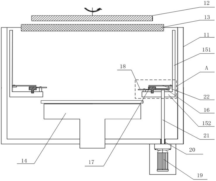
[0008] In view of the above-mentioned shortcomings of the prior art, the purpose of the present invention is to provide a physical vapor deposition equipment that can flexibly adjust the sputtering range to solve the problem that the existing design of the shadow ring structure will cause sticking and wafer fragmentation, or cause The equipment is bulky, which increases equipment cost and operating power consumption.

Method used


Image

  • Physical vapor deposition equipment capable of flexibly adjusting sputtering range
  • Physical vapor deposition equipment capable of flexibly adjusting sputtering range
  • Physical vapor deposition equipment capable of flexibly adjusting sputtering range

Examples


Embodiment Construction

[0027] The implementation of the present invention is illustrated by specific specific examples below, and those skilled in the art can easily understand other advantages and effects of the present invention from the content disclosed in this specification.

[0028] see Figure 1 to Figure 4 . It should be noted that the structures, proportions, sizes, etc. shown in the drawings attached to this specification are only used to match the content disclosed in the specification, for those who are familiar with this technology to understand and read, and are not used to limit the implementation of the present invention. Limiting conditions, so there is no technical substantive meaning, any modification of structure, change of proportional relationship or adjustment of size, without affecting the effect and purpose of the present invention, should still fall within the scope of the present invention. within the scope covered by the disclosed technical content. At the same time, te...


PUM


Abstract

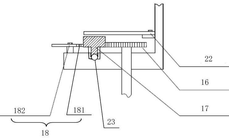
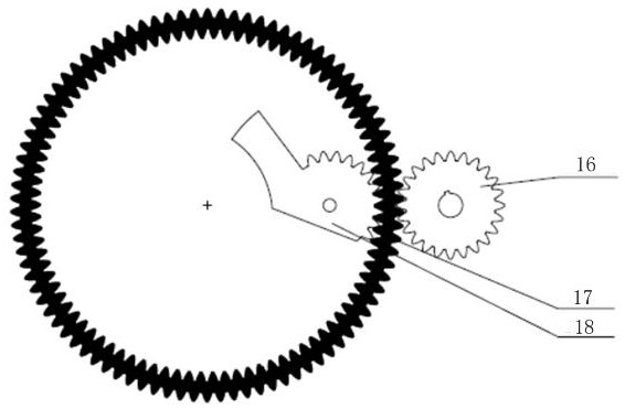
The invention provides physical vapor deposition equipment capable of flexibly adjusting the sputtering range. The physical vapor deposition equipment comprises a cavity, a sputtering device, a base, a baffle, a driving device, a driving gear, a transmission gear and multiple movable shielding units. The baffle comprises a first part and a second part, the first part is distributed in the circumferential direction of the cavity, one end of the second part is connected with the bottom of the first part, and the other end of the second part extends towards the center of the cavity. The driving gear is engaged with the transmission gear. The multiple movable shielding units are located on the inner side of the transmission gear, each movable shielding unit comprises an engagement part and a shielding part which are connected with each other, the engagement parts are engaged with the transmission gear, and the adjacent shielding parts are partially overlapped so that a sputtering channel can be formed on the inner sides of the shielding parts. The driving device is connected with the driving gear. When the driving gear is driven by the driving device to rotate, the transmission gear rotates under the engagement effect and drives the movable shielding units to rotate, and therefore the size of the sputtering channel is changed. The physical vapor deposition equipment is beneficial to improving coating uniformity.

Description

technical field [0001] The invention relates to the field of integrated circuits, in particular to a device for manufacturing integrated circuits, in particular to a physical vapor deposition device capable of flexibly adjusting the sputtering range. Background technique [0002] The coating process is an important process in the fabrication of semiconductor devices. Coating uniformity is crucial to product quality. It is not only one of the important indicators of film parameters, but also the core indicator of physical vapor deposition (PVD) equipment. The uniformity of the coating thickness has a great relationship with the target base distance (the distance between the sputtering target and the wafer base), the type of the magnet assembly above the target, and the gas flow rate. During the coating process, the wafer is placed on the base, the non-coated side is in contact with the base, and the coated side faces up to the target. For some power devices, packaging devic...

Claims


Application Information

Patent Timeline
Patent Type & Authority Applications(China)
IPC IPC(8): C23C14/35C23C14/54
CPCC23C14/35C23C14/54
Inventor 方合张慧崔世甲宋维聪
Owner BETONE TECH SUZHOU INC
Learn More