A high-brightness composite nickel plating layer
A technology of composite plating and nickel plating, applied in the direction of coating, silicon oxide, silicon dioxide, etc., to ensure the brightness and flatness, reduce the friction coefficient and improve the hardness
- Summary
- Abstract
- Description
- Claims
- Application Information
AI Technical Summary
Problems solved by technology
Method used
Image
Examples
Embodiment 1
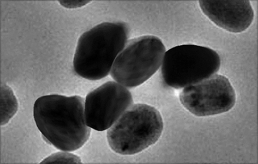
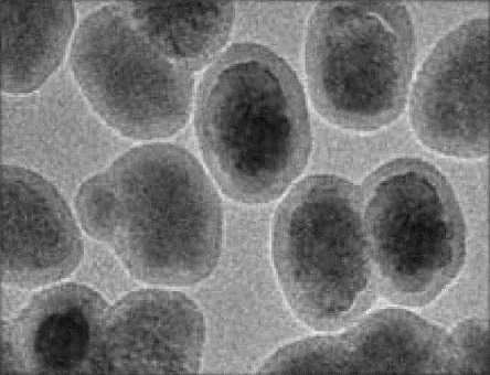
[0052] A method for preparing modified particles for composite electroplating. The modified particles are sulfide coated with silicon oxide. The specific preparation method is as follows.
[0053] (1) Put 1.5 g of molybdenum sulfide with a particle size of 75 nm and a purity greater than 99.8% in a three-necked flask, and add 45 mL of H 2 SO 4 and 10 mL of HNO with a mass fraction of 65%-67% 3 , sealed magnetic stirring for 15 min, heated in a water bath at 100 o C was refluxed for 4 h, washed with deionized water until neutral, and placed in an air furnace for 60 o C drying for 12 h to obtain mixed acid oxidation treated molybdenum sulfide particles.
[0054] (2) Weigh 1g of the molybdenum sulfide particles treated in step (1) into the three-necked flask, add 1ml of triethylamine in the there-necked flask, then slowly add dropwise and measure 50ml, 5mmol / L of azo-grafted agent solution, N 2 Protection, stirring at room temperature for 18h, washing with methanol multiple ...
Embodiment 2
[0059] A method for preparing modified particles for composite electroplating. The modified particles are sulfide coated with silicon oxide. The specific preparation method is as follows.
[0060] (1) Put 2 g of molybdenum sulfide with a particle size of 75 nm and a purity greater than 99.8% in a three-necked flask, and add 47.5 mL of H with a mass fraction of 98% 2 SO 4 and 12.5 mL of HNO with a mass fraction of 65%-67% 3 , sealed magnetic stirring for 17.5min, heated in a water bath at 100 o C was refluxed for 5 h, washed with deionized water until neutral, and placed in an air furnace at 65 o C drying for 15 h to obtain mixed acid oxidation treated molybdenum sulfide particles.
[0061] (2) Weigh 1.25g of the molybdenum sulfide particles treated in step (1) into the three-necked flask, add 1.5ml triethylamine into the three-necked flask, then slowly add dropwise and then measure 62.5ml, 10mmol / L azo Grafting agent solution, N 2 protection, stirring at room temperature ...
Embodiment 3
[0066] A method for preparing modified particles for composite electroplating. The modified particles are sulfide coated with silicon oxide. The specific preparation method is as follows.
[0067] (1) Put 2.5 g molybdenum sulfide with a particle size of 75 nm and a purity greater than 99.8% in a three-necked flask, and add 50 mL of H 2 SO 4 and 15 mL of HNO with a mass fraction of 65%-67% 3 , sealed magnetic stirring for 20 min, heated in a water bath at 100 o C was refluxed for 6 h, washed with deionized water until neutral, and placed in an air furnace for 70 o C drying for 18 h to obtain mixed acid oxidation treated molybdenum sulfide particles.
[0068] (2) Weigh 1-1.5g of molybdenum sulfide particles treated in step (1) into the three-necked flask, add 2ml of triethylamine into the three-necked flask, then slowly add dropwise and measure 75ml, 15mmol / L of azo Grafting agent solution, N 2 protection, stirring at room temperature for 24 hours, washing with methanol mul...
PUM
| Property | Measurement | Unit |
|---|---|---|
| hardness | aaaaa | aaaaa |
| particle diameter | aaaaa | aaaaa |
| hardness | aaaaa | aaaaa |
Abstract
Description
Claims
Application Information
 - R&D
- Intellectual Property
- Life Sciences
- Materials
- Tech Scout
- Unparalleled Data Quality
- Higher Quality Content
- 60% Fewer Hallucinations
Browse by: Latest US Patents, China's latest patents, Technical Efficacy Thesaurus, Application Domain, Technology Topic, Popular Technical Reports.
© 2025 PatSnap. All rights reserved.Legal|Privacy policy|Modern Slavery Act Transparency Statement|Sitemap|About US| Contact US: help@patsnap.com


