

Preventive maintenance method for asphalt concrete pavement
An asphalt concrete and preventive maintenance technology, applied in the direction of roads, roads, road repair, etc., can solve the problems of reducing maintenance efficiency, pavement performance recovery, segregation, etc., and achieve the effect of improving maintenance efficiency, enhancing pavement strength, and delaying asphalt aging.
- Summary
- Abstract
- Description
- Claims
- Application Information
AI Technical Summary
Problems solved by technology
Method used
Image

Examples
Embodiment Construction
[0044] The following is attached Figure 1-5 The application is described in further detail.
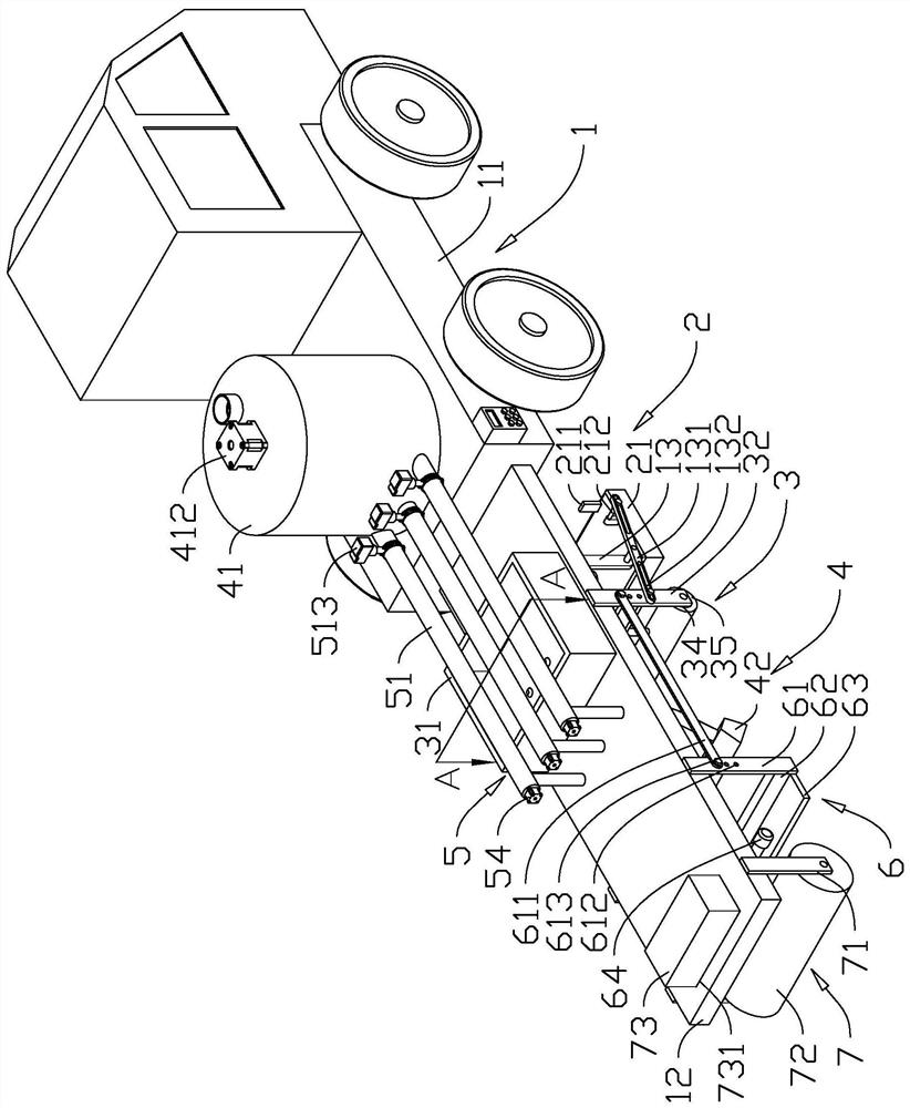
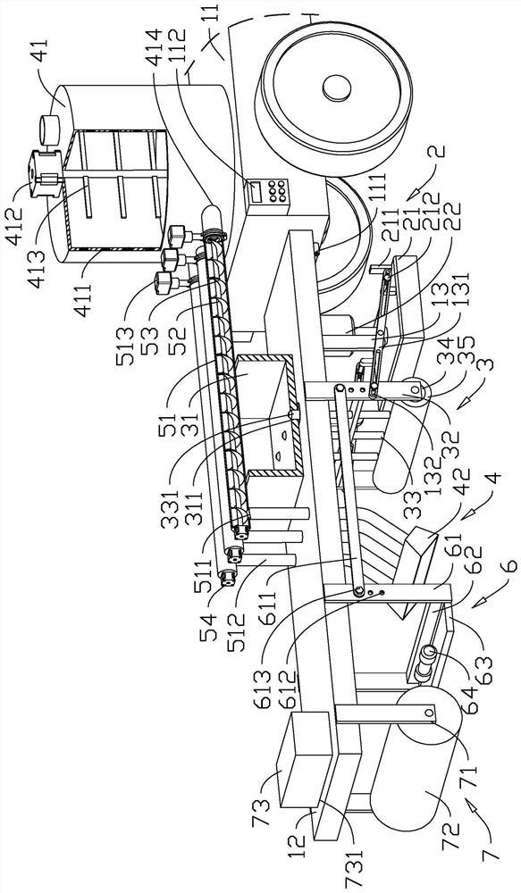
[0045] The embodiment of the present application discloses a preventive maintenance method for asphalt concrete pavement. refer to figure 1 , figure 2 , in the preventive maintenance method of asphalt concrete pavement, a maintenance vehicle 1 is used to maintain the asphalt concrete pavement. The maintenance vehicle 1 is provided with a heating mechanism 2, a maintenance mechanism 3, a covering mechanism 4, a leveling mechanism 6 and a compacting mechanism in sequence. Institution7. The maintenance vehicle 1 includes a vehicle body 11 and a support arm 12. The support arm 12 is arranged at the rear of the vehicle body 11, one end of which is connected to the vehicle body 11, and the other end extends away from the vehicle body 11, and is supported on the compacting mechanism 7 .
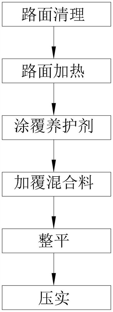
[0046] refer to figure 1 , the preventive maintenance method of asphalt concrete pavement includ...
PUM
 Abstract
Description
Claims
Application Information