
An artificial lake structure with self-purification function and its construction method

An artificial lake and self-purification technology, applied in sea area engineering, water conservancy engineering, climate change adaptation, etc., can solve problems such as complex terrain and terrain design, achieve good self-purification ability, reduce construction difficulty, and clearly separate the effect

Active Publication Date: 2022-06-17
中国华西企业股份有限公司
View PDF0 Cites 0 Cited by
  • Summary
  • Abstract
  • Description
  • Claims
  • Application Information

AI Technical Summary

Problems solved by technology

[0004] The first object of the present invention is to overcome the problem that existing artificial lakes have complex topography in order to ensure biological diversity and self-purification function, and provide an artificial lake structure with self-purification function, which is simple in structure and The design is reasonable, especially through the setting of the protection platform and the island reef area, it can ensure the relative independence of each area, ensure the living space of organisms, and at the same time achieve the purpose of the lake with self-purification function;
[0005] The second object of the present invention is to overcome the problem that existing artificial lakes have complicated terrain design in order to ensure biological diversity and self-purification function, and provide a construction method for the above-mentioned artificial lake structure, based on the planning and design of the artificial lake structure , can greatly shorten the construction period and reduce the difficulty of construction

Method used


Image

  • An artificial lake structure with self-purification function and its construction method
  • An artificial lake structure with self-purification function and its construction method
  • An artificial lake structure with self-purification function and its construction method

Examples


Embodiment

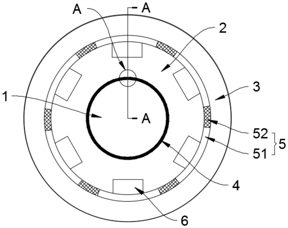
[0032] Please refer to figure 1 and image 3 , an artificial lake structure with self-purification function provided by this embodiment includes a groove-shaped space formed by a depression from a base surface, where the base surface mainly refers to the ground surface or the upper surface of other platforms erected on the foundation, In addition, the concave can be formed naturally or manually, as long as the space requirements for forming a concave or a concave are met. The trough-shaped space is at least divided into a shallow water area 1, a deep water area 2 and a transition area 3. Of course, more functional areas can also be planned. Here, several functional areas must be designed to achieve the purpose of the present invention. describe. Specifically, the deep water area 2 is located between the shallow water area 1 and the transition area 3, which means that the deep water area 2 isolates the shallow water area 1 and the transition area 3, which can reduce the influ...


PUM


Abstract

The invention discloses an artificial lake structure with self-purification function and a construction method thereof, and relates to the technical field of artificial lake construction. It includes at least a shallow water area, a deep water area and a transition area divided in a groove-shaped space, and the deep water area is located in the shallow water area. Between the shallow water area and the deep water area, there is an apron, between the transition area and the deep water area, there is an island reef area, and gravel is filled between the transition area and the tank wall of the trough space. The construction method is mainly carried out sequentially according to the planned locations of shallow water area, deep water area, island reef area and transition area. The invention has a simple structure and a reasonable design, especially through the setting of the protection platform and the island reef area, it can ensure the relative independence of each area, ensure the living space of organisms, and at the same time achieve the purpose of the lake having a self-purification function, and based on the artificial lake The planning and design of the structure can greatly shorten the construction period and reduce the difficulty of construction.

Description

technical field [0001] The invention relates to the technical field of artificial lake construction, in particular to an artificial lake structure with self-purification function and a construction method thereof. Background technique [0002] In order to save land, artificial lakes have greatly reduced the area of ​​shallow water at the edge of the lake. As a result, the lake is basically only a deep water area, lacking the support of the surrounding ecosystem, basically only storing water, lacking self-purification ability, and lacking ecological carrying capacity. Many lakes It even became a puddle of stagnant water. [0003] In view of the current situation of the artificial lake, it is necessary to improve the existing artificial lake configuration. Due to the small area and simple structure of the artificial lake, only a single species of each type of organism can survive, which is not conducive to the survival of animals. Diversity. Most of the existing methods are ...

Claims


Application Information

Patent Timeline
Patent Type & Authority Patents(China)
IPC IPC(8): E02B3/04E02B15/06
CPCE02B3/04E02B15/06E02B3/046Y02A10/26
Inventor 魏家刚王志强王顺藤
Owner 中国华西企业股份有限公司
Learn More