Two-dimensional half-bridge electro-hydraulic proportional directional valve based on push rod mid-mounted roller coupling

An electro-hydraulic proportional and center-mounted technology, which is applied in the direction of valve details, valve devices, and fluid pressure actuators, can solve problems such as the influence of electro-hydraulic proportional directional control valve response characteristics, increased maintenance costs, and shortened life of parts. Simple structure, long service life, and the effect of reducing axial size

Active Publication Date: 2021-06-18
ZHEJIANG UNIV OF TECH
View PDF8 Cites 2 Cited by
  • Summary
  • Abstract
  • Description
  • Claims
  • Application Information

AI Technical Summary

Problems solved by technology

The ball screw type coupling needs to accurately control the helix angle, otherwise it will be stuck, and the screw will be worn seriously, the life of the parts will be shortened, and the maintenance cost will increase; the elastic reed coupling is due to the elastic element Existence, which will have a great impact on the response characteristics of the electro-hydraulic proportional directional valve, and because the reed is subjected to bending moments during the working process, it will also affect the life of the parts, and it needs to be replaced regularly

Method used


Image

  • Two-dimensional half-bridge electro-hydraulic proportional directional valve based on push rod mid-mounted roller coupling
  • Two-dimensional half-bridge electro-hydraulic proportional directional valve based on push rod mid-mounted roller coupling
  • Two-dimensional half-bridge electro-hydraulic proportional directional valve based on push rod mid-mounted roller coupling

Examples


Embodiment Construction

[0035] The technical solution of the patent of the present invention will be clearly and completely described below in conjunction with the accompanying drawings. Apparently, the described embodiments are part of the embodiments of the present invention, not all of them. Based on the embodiments of the present invention, all other embodiments obtained by persons of ordinary skill in the art without making creative efforts belong to the protection scope of the present invention.

[0036] In the description of the present invention, it should be noted that if the terms "center", "upper", "lower", "left", "right", "vertical", "horizontal", "inner", "outer" appear ” and other indicated orientations or positional relationships are based on the orientations or positional relationships shown in the accompanying drawings, which are only for the convenience of describing the present invention and simplifying the description, rather than indicating or implying that the referred device or...


PUM


Abstract

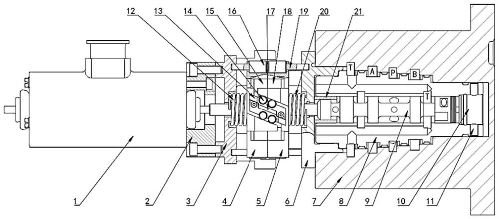
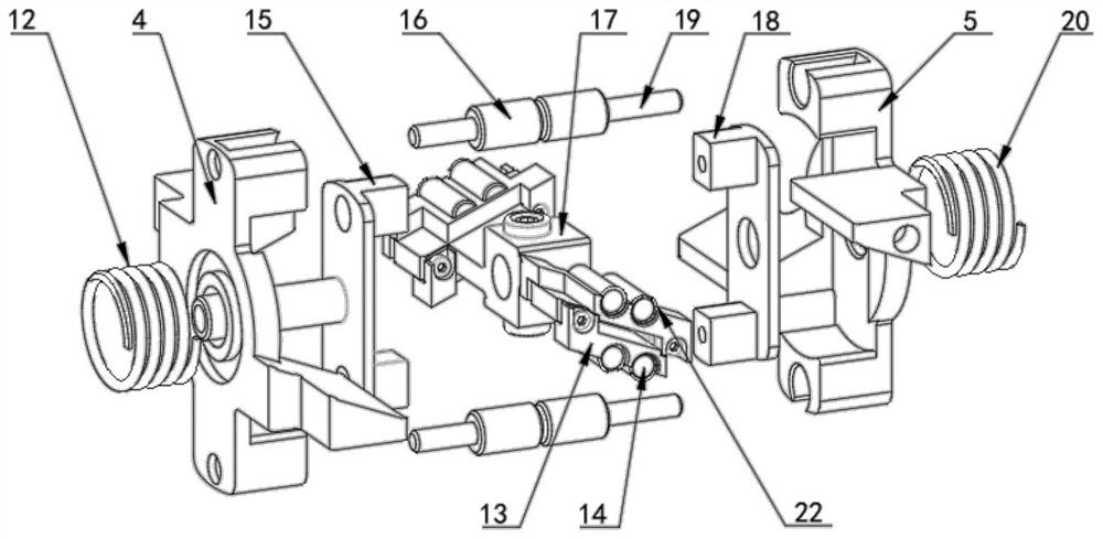
A two-dimensional half-bridge electro-hydraulic proportional directional valve based on a push rod mid-mounted roller coupling comprises a two-way proportional electromagnet, the push rod mid-mounted roller coupling and a two-dimensional half-bridge electro-hydraulic proportional directional valve body which are sequentially arranged from left to right, and the two-dimensional half-bridge electro-hydraulic proportional directional valve body comprises a valve body, a valve sleeve and a valve element. The two-way proportional electromagnet is mounted at the left end of the valve body, the push rod mid-mounted roller coupling is mounted at the left end of the valve element, and the valve element is connected with the two-way proportional electromagnet through the push rod mid-mounted roller coupling. A two-dimensional hydraulic amplification mechanism with two degrees of freedom of the valve element is adopted, rotation of the valve element serves as a pilot level, axial movement of the valve element serves as a power level, the pilot level and the power level are integrated on the single valve element, the structure is simple, the machining cost is low, and the power-to-weight ratio is greatly increased.

Description

technical field [0001] The invention relates to a directional control valve for electro-hydraulic proportional control technology in the field of fluid transmission and control, in particular to a two-dimensional half-bridge electro-hydraulic proportional reversing valve based on a push rod centered roller coupling. Background technique [0002] Hydraulic transmission technology has been applied to various cranes and presses with the Pascal principle since the 1950s. It has a history of nearly 200 years. At this stage, hydraulic technology and microelectronics technology have been combined. Transmission of as much power as possible in space and precise control, hydraulic technology has made significant progress in achieving high efficiency, high power, low noise, high speed, high pressure, highly integrated, intelligent and other aspects, key applications It is used in industrial occasions such as military weapons, aerospace, ships and oceans, steel smelting, forging and cas...

Claims


Application Information

Patent Timeline
Patent Type & Authority Applications(China)
IPC IPC(8): F16K31/06F15B13/02
CPCF16K31/0675F16K31/0627F15B13/02
Inventor 孟彬杨冠政徐豪朱良强衡垚圳
Owner ZHEJIANG UNIV OF TECH
Why Eureka
Try Eureka