A binocular measurement system, method and device for obtaining the size of automobile parts

A technology for auto parts and measurement systems, which is applied in image analysis, image enhancement, instruments, etc., can solve the problems of complex size measurement steps, large measurement errors, and small shooting range of auto parts, and achieves easy measurement of geometric information and high practicability. , the effect of improving the accuracy

Active Publication Date: 2021-09-28
HARBIN INST OF TECH
View PDF14 Cites 0 Cited by
  • Summary
  • Abstract
  • Description
  • Claims
  • Application Information

AI Technical Summary

Problems solved by technology

[0003] The purpose of the present invention is to solve the problem of complex measurement steps and large measurement errors of auto parts due to the small single shooting range of 3D sensors, and propose a binocular measurement system, method and method for obtaining auto parts sizes. device

Method used


Image

  • A binocular measurement system, method and device for obtaining the size of automobile parts
  • A binocular measurement system, method and device for obtaining the size of automobile parts
  • A binocular measurement system, method and device for obtaining the size of automobile parts

Examples


specific Embodiment approach 1

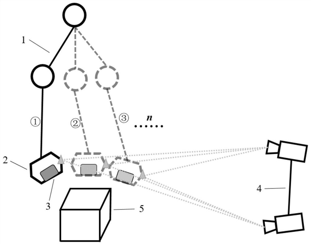
[0023] DETAILED DESCRIPTION OF THE PREFERRED EMBODIMENT 1. A binocular measurement system for obtaining the size of automobile parts described in this embodiment, the system includes: a mechanical arm 1, a three-dimensional calibration target 2, a 3D sensor 3, a binocular camera 4, a measured Auto parts5 and computers, of which:

[0024] The three-dimensional calibration target 2 is fixed on the end of the mechanical arm 1 together with the 3D sensor 3, and the binocular camera 4 is fixed on the side of the mechanical arm 1 for taking images of the three-dimensional calibration target 2 and sending the captured images to to the computer;

[0025] The 3D sensor 3 is used to collect point cloud information on the surface of the measured automobile part 5, and the collected point cloud information is sent to a computer;

[0026] The computer is used to process the captured images to obtain the conversion matrix from the stereo calibration target 2 to the binocular camera 4, and ...

specific Embodiment approach 2

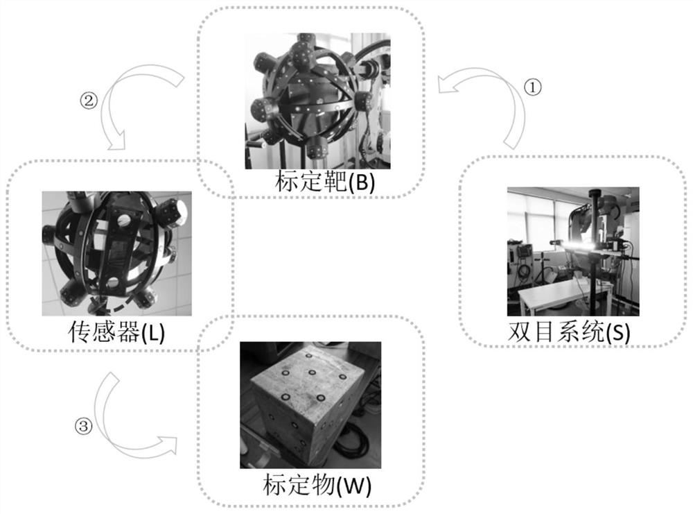
[0027] Embodiment 2. The difference between this embodiment and Embodiment 1 is that the conversion of the point cloud information collected by the 3D sensor 3 into the binocular camera coordinate system also requires the use of the transformation matrix from the 3D sensor 3 to the stereo calibration target 2. , the conversion matrix from the 3D sensor 3 to the stereo calibration target 2 is obtained by calibrating the stereo calibration target 2 and the 3D sensor 3 .

specific Embodiment approach 3

[0028] Specific embodiment three, based on the binocular measurement method of a binocular measurement system for obtaining the size of automobile parts described in specific embodiment one, the method is specifically implemented through the following steps:

[0029] Calibrate the stereo calibration target 2 and the 3D sensor 3, and obtain a conversion matrix from the 3D sensor 3 to the stereo calibration target 2 according to the calibration;

[0030] The computer processes the image of the stereo calibration target 2 taken by the binocular camera 4 to obtain a conversion matrix from the stereo calibration target 2 to the binocular camera 4;

[0031] After the 3D sensor 3 collects the point cloud information on the surface of the measured automobile part 5, according to the obtained transformation matrix from the 3D sensor 3 to the stereo calibration target 2 and from the stereo calibration target 2 to the binocular camera 4, the 3D sensor 3 collects The point cloud informati...


PUM


Abstract

The invention discloses a binocular measurement system, method and device for acquiring the dimensions of automobile parts, belonging to the field of robot vision detection. The invention solves the problems of complicated measurement steps of the size of the automobile parts and large measurement errors caused by the small single shooting range of the 3D sensor. The invention introduces the combination of binocular vision and 3D sensor for industrial detection, and the measurement steps are relatively simple. The point cloud captured by the 3D sensor can be uniformly transformed into the binocular coordinate system for calculation, which is convenient for measurement, especially for large parts, only need to use binocular The eye system can complete the coordinate conversion of the complete point cloud of the measured auto parts by tracking the three-dimensional calibration target at the end of the robot multiple times, which is convenient for measuring geometric information, convenient and fast, and has high practicability. The error of size measurement is reduced. The invention can be used for measuring the size of automobile parts.

Description

technical field [0001] The invention belongs to the field of robot vision detection, and in particular relates to a binocular measurement system, method and device for obtaining the size of automobile parts. Background technique [0002] At present, in visual measurement, 3D sensors have been widely used in factory automation, quality inspection and process optimization, providing actionable data for industrial networks and dynamic manufacturing processes. But the disadvantage is that the shooting range of the 3D sensor is small. For auto parts with large size and many sizes to be measured, it is difficult to complete a single measurement. You can only measure a small part each time, and then match the common points of each measurement. , and then combined into a complete point cloud for comparison, which greatly increases the error in the size measurement of auto parts, and the measurement process is more complicated. As a better non-contact measurement method, binocular v...

Claims


Application Information

Patent Timeline
Patent Type & Authority Patents(China)
IPC IPC(8): G06T7/80G06T7/60
CPCG06T7/60G06T2207/10012G06T7/85
Inventor 吴立刚王艳坤孙光辉付金宇张兵刘越
Owner HARBIN INST OF TECH
Why Eureka
Try Eureka