
Method for improving output linearity of digital phase converter

An output linearity, converter technology, applied in the direction of automatic power control, electrical components, etc., can solve problems such as phase interpolator linearity, and achieve the effect of optimized linearity and high linearity

Active Publication Date: 2021-06-18
SHANGHAI JIAO TONG UNIV
View PDF9 Cites 0 Cited by
  • Summary
  • Abstract
  • Description
  • Claims
  • Application Information

AI Technical Summary

Problems solved by technology

[0003] Aiming at the above-mentioned deficiencies in the prior art, the present invention proposes a method for improving the output linearity of a digital phase converter, which can solve the linearity problem of the phase interpolator

Method used


Image

  • Method for improving output linearity of digital phase converter
  • Method for improving output linearity of digital phase converter
  • Method for improving output linearity of digital phase converter

Examples


Embodiment Construction

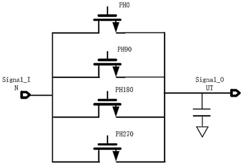
[0016] Such as figure 1 As shown, in this embodiment, an N-channel filter is added to the traditional digital phase conversion circuit, and the filter is modulated to the target frequency in a loop-on manner, thereby improving the linearity of the digital phase converter.

[0017] Such as figure 2 As shown, the phase interpolator uses a multi-phase clock as the control clock of the N-channel filter.

[0018] Because of the same frequency as the processed signal, the bandpass frequency point can accurately follow the frequency of the clock signal processed by the digital phase converter.

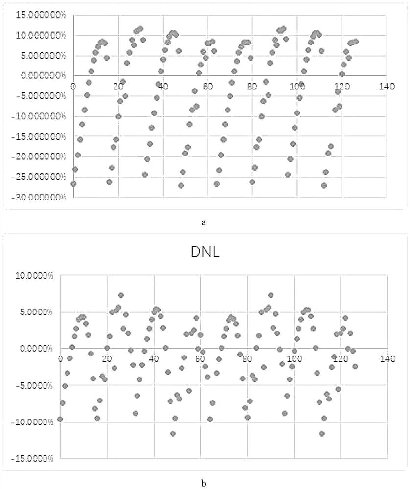
[0019] When the N-channel filter is turned on and off, the digital phase converter using the N-channel filter is compared with the two modes of short-circuiting the N-channel filter in the same digital phase converter to make it lose its effect, and the output phase Scan with the input digital value, and perform differential nonlinear (DNL) conversion on the obtained data. The conversion f...


PUM


Abstract

A method for improving output linearity of a digital phase converter is characterized in that an N-channel filter is additionally arranged in a phase interpolation circuit in the digital phase converter, and the N-channel filter takes a multi-phase clock generated by a delay locked loop in the digital phase converter as a control clock and modulates the control clock to a target frequency in a circulating opening mode; therefore, the linearity of the digital phase converter is improved, wherein N is an integral multiple of 4. The linear problem of the phase interpolator can be solved.

Description

technical field [0001] The invention relates to a technology in the field of digital signal processing, in particular to a method for improving output linearity of a digital phase converter. Background technique [0002] In the system, it is often necessary to use a digital phase converter to generate a clock with a specified phase. According to an input clock, N phases in 0-360 degrees are generated (determined by the number of input digits). Every time the input digital value increases by 1, the generated phase will step forward by one grid, but due to the non-ideality of the phase interpolator itself in the digital phase converter, the step size of each grid phase is not uniform, that is, the digital value and the corresponding The resulting phase-to-phase nonlinearity. In the prior art, ideal output clocks with different phases are obtained by changing weight coefficients, but in actual circuits, the clock signal is not a pure sinusoidal signal. The interference of ot...

Claims


Application Information

Patent Timeline
Patent Type & Authority Applications(China)
IPC IPC(8): H03L7/085
CPCH03L7/085
Inventor 周健军丁力刘晓鸣金晶
Owner SHANGHAI JIAO TONG UNIV
Learn More