Metal scrap removing device for lathe

A technology of metal waste and removal device, which is applied in the direction of metal processing equipment, metal processing machinery parts, maintenance and safety accessories, etc., can solve the problems of small debris blowing into the lathe gap, environmental pollution, waste of resources, etc., to avoid waste , Easy to use, simple operation

Active Publication Date: 2021-06-22
周晓勇
24 Cites 0 Cited by

AI-Extracted Technical Summary

Problems solved by technology

On the lathe, drill bits, reamers, reamers, screw taps, dies and knurling tools, etc. can also be used for corresponding processing; when lathes are processing ferrous metals, a large amount of metal debris can be produced, although the lathes are equipped with There are structures for collecting fallen metal chips, but the existing metal chip collection structures for lathes can only collect large pieces of dropped metal chips, and the...

Method used

Use energized wire 21 to be electrically connected with power supply module 7, for magnetic adsorption assembly and multiple groups of magnetic telescopic assemblies to supply power; energized wire 21 is positioned at protective tube 19 to carry out protection to energized wire 2...

Abstract

The invention discloses a metal scrap removing device for a lathe. The metal scrap removing device comprises a box body, two sets of quick connectors, a connecting pipe and a shell; the interior of the box is divided into a mounting bin and a collecting bin through a partition plate; the collecting bin is provided with a filter screen in an exhaust hole formed in the end face of the box body; a drawer is slidably arranged in the collecting bin; a high-pressure fan is arranged in the mounting bin; the lower end face of the shell is provided with an opening; a first rolling assembly is arranged on the bottom face of the shell; a second rolling assembly is arranged on the side end face of the shell; a magnetic adsorption assembly used for magnetically adsorbing iron-containing metal scraps is arranged in the shell, and a plurality of sets of magnetic telescopic assemblies used for driving the magnetic adsorption assembly to move towards or away from the opening are arranged in the shell; the connecting pipe comprises a protective pipe and an air pipe; the protective pipe sleeves the outer side of the air pipe, and the two ends of the protective pipe are connected with the outer end face of the box body and the outer end face of the shell through two sets of quick connectors correspondingly; and the air pipe and the high-pressure fan communicate with the shell and the collecting bin. The device is easy and convenient to operate, and iron metal scraps remaining on a precision machine tool can be collected conveniently.

Application Domain

Maintainance and safety accessories

Technology Topic

ScrapIron metal +4

Image

  • Metal scrap removing device for lathe
  • Metal scrap removing device for lathe
  • Metal scrap removing device for lathe

Examples

  • Experimental program(1)

Example Embodiment

[0051] In order to make the object, technical solution and advantages of the present invention clearer, the present invention will be further described in detail below in combination with specific embodiments and with reference to the accompanying drawings. It should be understood that these descriptions are exemplary only, and are not intended to limit the scope of the present invention. Also, in the following description, descriptions of well-known structures and techniques are omitted to avoid unnecessarily obscuring the concept of the present invention.
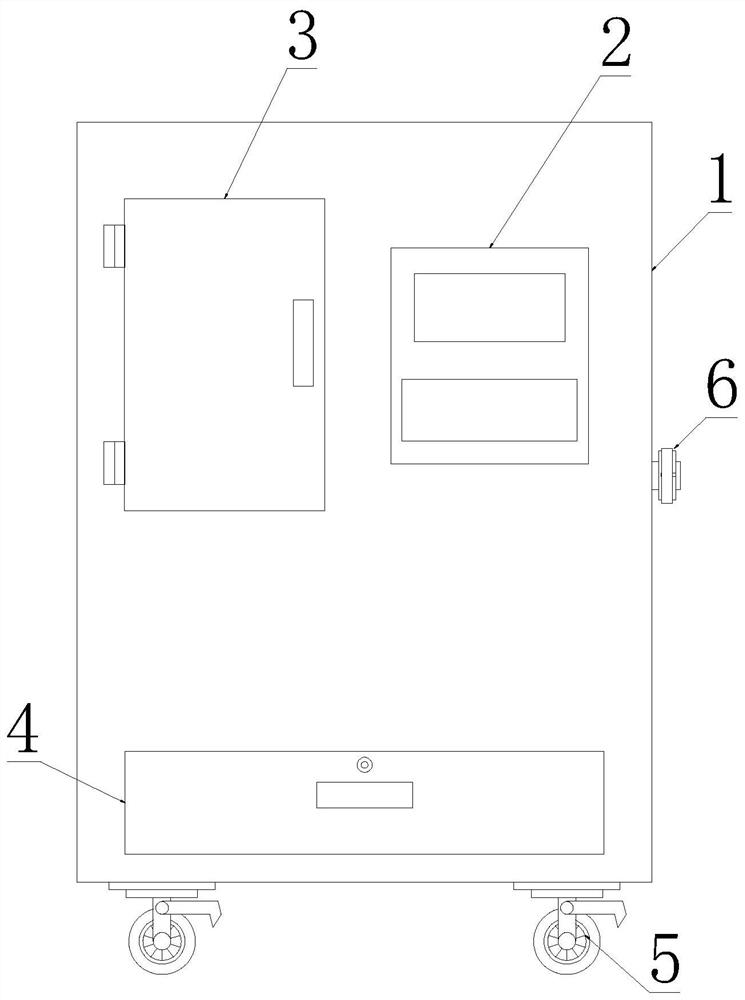
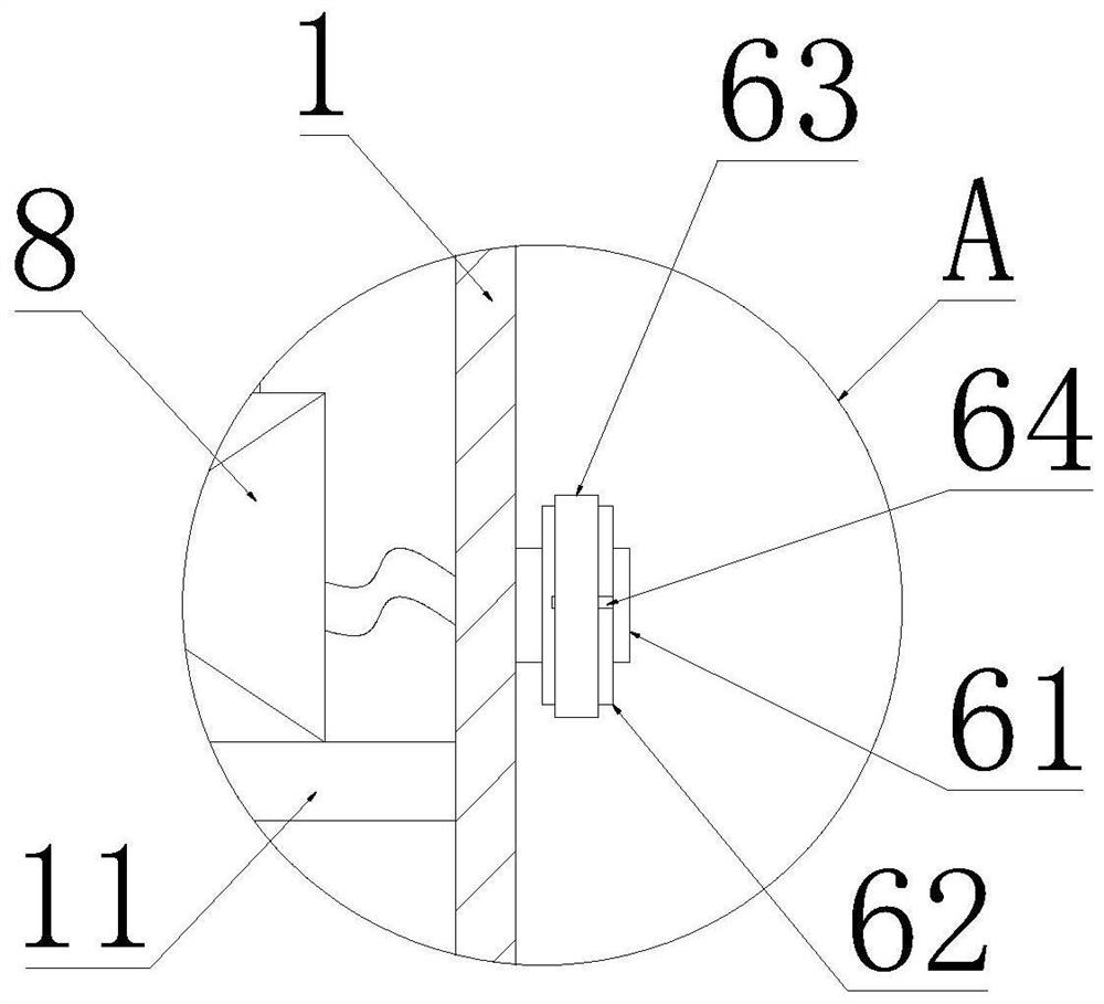
[0052] like Figure 1-12 As shown, a metal scrap removal device for a lathe proposed by the present invention includes a box body 1, a control box 2, two groups of quick connectors 6, connecting pipes and a housing 10;
[0053] A partition 11 is provided inside the cabinet 1; the partition 11 is horizontally distributed to divide the interior of the cabinet 1 into an upper installation bin 9 and a lower collection bin, and the partition 11 is provided with a collection hole;
[0054] The collection bin is provided with a vent hole on the end face of the box body 1; a filter screen 12 is provided in the vent hole; a drawer 4 is slidingly provided in the collection bin; Chips are collected, the drawer 4 is slidingly connected to the inner wall of the collection bin, and the drawer 4 is connected to the box body 1 through a lock to make the seal between the drawer 4 and the box body 1; this is the prior art and will not be described in detail;
[0055] The installation warehouse 9 is provided with a first air hole on the box body 1, and a high-pressure blower 8 is arranged in the installation warehouse 9; The side end is provided with a sealed door 3; the sealed door 3 is provided with a concave handle, and one end of the sealed door 3 is connected to the box body 1 through a hinge, and the sealed door 3 is connected to the box body 1 through a lock; the installation warehouse 9 is used for storing appliances Such as the shell 10 and connecting pipes in the non-use state;
[0056] The outer end surface of the casing 10 is provided with a handle 101, the casing 10 is provided with a second air hole, the lower end surface of the casing 10 is provided with an opening 16, and two groups of adjacent side end surfaces of the casing 10 are provided with grooves 102 on the bottom surface of the casing 10. The two groups of grooves 102 are all communicated with the opening 16; the bottom surface of the housing 10 is provided with a first rolling assembly, and any group of grooves 102 is provided with a second rolling assembly on the side end surface of the housing 10; A magnetic adsorption assembly for magnetically adsorbing ferrous metal scraps. The housing 10 is provided with multiple sets of magnetic telescopic assemblies for driving the magnetic adsorption assembly to move toward or away from the opening 16;
[0057] The connecting pipe includes a protective pipe 19 and an air pipe 20; the protective pipe 19 is sleeved on the outside of the air pipe 20, the inner wall of the protective pipe 19 is connected to the outer peripheral surface of the air pipe 20, and the two ends of the protective pipe 19 are respectively connected to the box body 1 through two sets of quick connectors 6 The outer end face of the outer end face and the outer end face of the shell 10; two groups of quick joints 6 are respectively connected to the box body 1 and the shell 10; the two ends of the air pipe 20 are respectively connected to the first air hole and the second air hole;
[0058] The control box 2 is connected to the outer end face of the casing 1, and the control box 2 is provided with a display and a button module, and the control box 2 is provided with a controller 37; the controller 37, the high-pressure fan 8, the display, the button module, magnetic adsorption components and multiple The group of magnetic telescopic components is electrically connected.
[0059] In the present invention, when it is necessary to clean up debris on precision machine tools, start the high-pressure blower 8, the magnetic adsorption assembly and multiple sets of magnetic telescopic assemblies; the multiple sets of magnetic telescopic assemblies drive the magnetic adsorption assembly to move toward the opening 16 of the housing 10. With the handle 101, the bottom surface of the shell 10 provided with the opening 16 faces the machine tool, and the ferrous metal debris remaining on the machine tool is adsorbed by the magnetic adsorption assembly provided, and the high-pressure blower 8 operates to suck the impurities on the machine tool into the shell 10, The iron impurities in the impurities are further adsorbed on the magnetic adsorption component, and the impurities are transported to the collection bin by the air pipe 20, and finally the impurities are collected in the drawer 4; after the iron impurities are adsorbed, the shell 10 is moved to the side of the machine tool At the iron filings collection box, the magnetic adsorption components and multiple sets of magnetic telescopic components are powered off, and the impurities adsorbed on the magnetic adsorption components are separated from them and fall into the collection box, which is easy to operate and convenient to use.
[0060] In an optional embodiment, the bottom surface of the box body 1 is provided with multiple sets of universal wheels 5; further, the universal wheels 5 are universal wheels with brakes; the use of the universal wheels 5 facilitates the movement of the box body 1;
[0061] Further, a collection box is stored in the installation compartment 9 of the box body 1; when in use, the collection box is taken out and placed on the top of the box body 1 to collect iron filings impurities after magnetic adsorption.
[0062] In an optional embodiment, it also includes a power module 7, a power lead 21 and a control switch; wherein, the outer end surface of the shell 10 and the outer end surface of the box body 1 are provided with sockets; a group of sockets are electrically connected to the power module 7 ; The power module 7 is installed in the installation compartment 9; another set of sockets is electrically connected to the magnetic adsorption component and multiple sets of magnetic telescopic components;
[0063] The energizing wire 21 is located inside the protective tube 19, and the two ends of the energizing wire 21 are respectively provided with plugs; two sets of plugs are matched to connect two groups of sockets respectively;
[0064] The control switch is installed on the handle 101, and the control switch, the magnetic adsorption component, multiple sets of magnetic telescopic components, the power module 7, the high-pressure blower 8 and the controller 37 are electrically connected;
[0065] Use energized lead 21 to be electrically connected with power supply module 7, supply power for magnetic adsorption component and multiple sets of magnetic telescopic components; Disassembly and assembly are more convenient.
[0066] In an optional embodiment, it also includes multiple sets of first fasteners and two sets of first flanges; wherein, second flanges are provided on the outer end surface of the housing 10 and the outer end surface of the box body 1;
[0067] The two sets of first flanges are respectively connected to the nozzles at both ends of the gas pipe 20, and the two sets of first flanges are respectively connected to two sets of second flanges through multiple sets of first fasteners;
[0068] The air pipe 20 is fixedly installed through the cooperation of the provided first flange and the second flange, thereby facilitating disassembly and assembly of the air pipe 20 .
[0069] In an optional embodiment, it also includes two groups of material guide plates 13; one end of the two groups of material guide plates 13 is connected to the inner wall of the collection bin, and the other end of the two groups of material guide plates 13 is facing downward towards the bottom of the collection bin It is arranged obliquely, and there is a space for metal scraps to fall between the two sets of material guide plates 13;
[0070] The two sets of material guide plates 13 are provided to facilitate the impurities entering the collection bin to quickly fall into the drawer 4 .
[0071] In an optional embodiment, each set of quick joints 6 includes a mounting cylinder 61, a clamping cylinder 62 and a fastener 63;
[0072] The installation cylinder 61 is connected to the shell 10 or the box body 1; the second air hole or the first air hole is located inside the installation cylinder 61; the inner diameter of the clamping cylinder 62 is greater than the outer diameter of the installation cylinder 61, and the sleeve of the clamping cylinder 62 is set in the installation The outside of the cylinder 61 is connected to the installation cylinder 61, and there is an installation space for the interference sleeve of the protective tube 19 on the outside of the installation cylinder 61 between the inner wall of the clamping cylinder 62 and the outer wall of the installation cylinder 61; wherein, the clamping cylinder 62 A plurality of sets of slits 64 are evenly provided on the outer peripheral surface, and external threads are provided on the outer peripheral surface of the clamping cylinder 62;
[0073] The fastener 63 is provided with a fastening bin along the central axis direction; the inner diameter of the fastening bin along the central axis direction gradually decreases, and internal threads are provided on the inner wall of the fastening bin; the fastening bin is threadedly connected by the provided internal thread The external thread provided on the clamping cylinder 62 is used to shrink the clamping cylinder 62 to clamp the protective tube 19;
[0074] When in use, one end of the trachea 20 is connected to the second air hole or the first air hole, the protective tube 19 is sleeved on the outside of the installation tube 61, and the fastener 63 is rotated to shrink the clamping tube 62 to compress the protective tube 19 On the outside of the installation cylinder 61, the protective tube 19 is further fixed;
[0075] Further, an elastic pad is provided on the inner wall of the clamping cylinder 62 to protect the protection tube 19 .
[0076] In an optional embodiment, the first rolling assembly includes multiple sets of mounting blocks 15, multiple sets of first balls 23 and multiple sets of second fasteners; wherein, the bottom surface of the housing 10 is provided with multiple sets of first threaded blind holes ;
[0077] Multiple groups of mounting blocks 15 are provided with flange plates along the outer peripheral direction; each group of flange plates is provided with multiple groups of first through holes; multiple groups of second fasteners pass through multiple groups of first through holes respectively. The holes are screwed into multiple sets of first threaded blind holes; multiple sets of mounting blocks 15 are pressed against the bottom surface of the shell 10 toward the end face of the bottom surface of the shell 10, and the end faces of each set of mounting blocks 15 and the shell 10 are provided with first Accommodating slots; the end surface of the housing 10 and the mounting block 15 is pressed with a second accommodating slot; each set of second accommodating slots and each set of first accommodating slots communicate with each other to form a first accommodating slot for placing each set of first balls 23 warehouse; each group of first storage chambers is provided on the end face of each group of mounting blocks 15 away from the housing 10 for allowing the partial spherical surface of each group of first balls 23 to pass through the second through hole 17;
[0078] When in use, the plurality of sets of first balls 23 are in contact with the end surface of the machine tool, thereby facilitating the movement of the housing 10 on the machine tool, which is more convenient.
[0079] In an optional embodiment, the second rolling assembly includes a mounting plate 14, multiple sets of second balls 22 and multiple sets of third fasteners; wherein, the side end surface of the housing 10 is provided with multiple sets of second threaded blind holes;
[0080] Multiple sets of fourth through holes 18 are provided on the mounting plate 14; multiple sets of third fasteners respectively pass through multiple sets of fourth through holes 18 and threaded into multiple sets of second threaded blind holes; the mounting plate 14 faces the housing 10 The end face of the shell 10 is compressed, and the mounting plate 14 and the end face of the shell 10 are provided with multiple sets of third receiving grooves; the end faces of the mounting plates 14 of the shell 10 are provided with multiple sets of fourth containing grooves; The fourth receiving grooves correspond one-to-one to multiple groups of third receiving grooves and communicate with each other to form a second housing bin for placing multiple groups of second balls 22; There are multiple groups for each group of second balls 22 to partially pass through the third through hole 141;
[0081]When in use, multiple sets of second balls 22 are brought into contact with the vertical end faces of the machine tool and multiple sets of first balls 23 are brought into contact with the horizontal end faces of the machine tool, and the housing 10 is moved to facilitate the cleaning of impurities remaining on the vertical edges of the machine tool. The plurality of sets of second balls 22 prevents the side end faces of the housing 10 from contacting with the end face of the machine tool and impurity from wearing the housing 10 .
[0082] In an optional embodiment, the magnetic adsorption assembly includes multiple sets of magnetic boxes 24, multiple sets of solenoids 25, and multiple sets of insulating rods 27; multiple sets of insulating rods 27 are slidably connected to the inner wall of the housing 10;
[0083] Multiple groups of solenoids 25 are respectively installed in multiple groups of magnetic boxes 24, and multiple groups of solenoids 25 are wound with multiple groups of wires 26; when multiple groups of wires 26 are energized, multiple groups of magnetic boxes 24 are magnetic; multiple groups of magnetic boxes 24 are distributed side by side, and the upper end surface of each group of magnetic boxes 24 is provided with a curved surface; multiple groups of insulating rods 27 are distributed side by side, and the length direction of multiple groups of insulating rods 27 is perpendicular to the length direction of multiple groups of magnetic boxes 24 respectively, and multiple groups of insulating rods 27 Connect multiple sets of magnetic telescopic components separately;
[0084] During use, under the energized state of multiple groups of wires 26, the multiple groups of magnetic boxes 24 have magnetism to adsorb ferrous impurities, and the multiple groups of magnetic boxes 24 are driven by multiple groups of magnetic telescopic components to make the connection between the multiple groups of magnetic boxes 24 and the machine tool The distance between them is reduced to improve the adsorption effect on iron impurities.
[0085] In an optional embodiment, each group of magnetic telescopic components includes a sliding rod 28, a fixed cylinder 29, an elastic sleeve 32, a limit plate 33, multiple sets of springs 34 and a fixed magnet 36;
[0086] One end of the fixed cylinder 29 is connected to the inner wall of the housing 10, and the other end of the fixed cylinder 29 is provided with a fifth through hole;
[0087] One end of the slide rod 28 is connected to the magnetic adsorption assembly, and the other end of the slide rod 28 slides through the limit plate 33 and the fifth through hole and is inserted into the fixed cylinder 29, and the slide rod 28 in the fixed cylinder 29 is provided with a moving magnet 35; A wire frame 31 is provided between the moving magnet 35 and the inner wall of the fixed cylinder 29; the wire frame 31 is connected to the inner wall of the fixed cylinder 29, and the wire frame 31 is provided with a coil 30; ;
[0088] The fixed magnet 36 is connected to the inner wall of the fixed cylinder 29, and the fixed magnet 36 is sleeved on the outside of the slide bar 28; when the coil 30 is energized, the fixed magnet 36 and the moving magnet 35 are connected by magnetic adsorption;
[0089] Multiple groups of springs 34 are sleeved on the outside of the slide bar 28, and the two ends of the springs 34 are respectively connected to the outer end surfaces of the limit plate 33 and the fixed cylinder 29; The ends are respectively connected to the limit plate 33 and the fixed cylinder 29;
[0090] During use, coil 30 is energized, and the magnetic field that it produces conducts to fixed magnet 36, and under the magnetic force attraction of fixed magnet 36, moving magnet 35 and slide bar 28 move to the direction where fixed magnet 36 is, and multiple groups of springs 34 are compressed, more The group of sliding rods 28 drives the magnetic adsorption assembly to move; after the coil 30 is powered off, the moving magnet 35 and the sliding rod 28 return to their original positions under the action of multiple sets of springs 34;
[0091] Further, multiple sets of magnetic telescopic components and magnetic adsorption components are electrically connected.
[0092] It should be understood that the above specific embodiments of the present invention are only used to illustrate or explain the principles of the present invention, and not to limit the present invention. Therefore, any modification, equivalent replacement, improvement, etc. made without departing from the spirit and scope of the present invention shall fall within the protection scope of the present invention. Furthermore, it is intended that the appended claims of the present invention embrace all changes and modifications that come within the scope and metesques of the appended claims, or equivalents of such scope and metes and bounds.

PUM

no PUM

Description & Claims & Application Information

We can also present the details of the Description, Claims and Application information to help users get a comprehensive understanding of the technical details of the patent, such as background art, summary of invention, brief description of drawings, description of embodiments, and other original content. On the other hand, users can also determine the specific scope of protection of the technology through the list of claims; as well as understand the changes in the life cycle of the technology with the presentation of the patent timeline. Login to view more.

Similar technology patents

Laser radar optical system with optical axis calibrating function and optical axis calibrating method

InactiveCN102353950AOptical axis alignment with high precisioneasy to operate
Owner:INST OF APPLIED ELECTRONICS CHINA ACAD OF ENG PHYSICS +1

Defrosting control method and device

ActiveCN104807132Aeasy to operateDefrost is reasonable
Owner:GREE ELECTRIC APPLIANCES INC OF ZHUHAI

Classification and recommendation of technical efficacy words

  • easy to operate
  • easy to use

Lancet device

InactiveUS7303573B2inexpensively mass-producedeasy to operate
Owner:ABBOTT DIABETES CARE INC

Rapid and non-invasive optical detection of internal bleeding

InactiveUS20050065436A1easy to operaterapid and accurate result
Owner:HO WINSTON ZONH +2

Laser assisted total joint arthroplasty

InactiveUS20090234360A1easy to use
Owner:ALEXANDER VLADIMIR

Enclosure for a portable hemodialysis system

ActiveUS20090114582A1easy to use
Owner:DEKA PROD LLP
Why Eureka
Try Eureka