
Coal mine goaf treatment and collapse backfill slurrying and grouting device

A technology for grouting devices and gobs, applied in safety devices, fillings, mining equipment, etc., can solve the problems of difficulty in sealing grouting holes, high labor intensity of workers, small construction space, etc., and achieve space saving , Reduce labor intensity and save cost

Active Publication Date: 2021-06-22
徐州中矿岩土技术股份有限公司
View PDF13 Cites 9 Cited by
  • Summary
  • Abstract
  • Description
  • Claims
  • Application Information

AI Technical Summary

Problems solved by technology

[0004] In order to solve the above technical problems, the present invention provides a coal mine goaf treatment and subsidence backfill grouting grouting device to solve the problems of low work efficiency, high labor intensity of workers, and small construction space during the entire use process. Solved the problem that the grouting hole cannot be continuously sealed and the sealing is difficult after the grouting is completed

Method used


Image

  • Coal mine goaf treatment and collapse backfill slurrying and grouting device
  • Coal mine goaf treatment and collapse backfill slurrying and grouting device
  • Coal mine goaf treatment and collapse backfill slurrying and grouting device

Examples


Embodiment 1

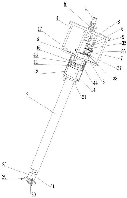
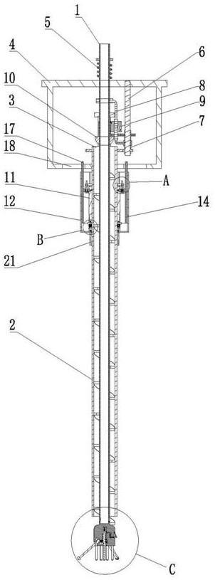
[0025]Embodiment 1, a grouting device for coal mine goaf control and subsidence backfilling, including a screw rod 1 with a vertical axis, the screw rod 1 is a hollow structure, and the upper end of the screw rod 1 is connected with a drilling machine. Take the machine to support and drive the screw rod 1. The upper end of the screw rod 1 is connected with the grouting pump. The grouting pump is used for grouting after drilling. The outer wall of the screw rod 1 is surrounded by spiral blades. The first cylinder 2 is sleeved, the screw blade is placed in the first cylinder 2, the part without the helical blade at the upper end of the screw rod 1 is placed above the first cylinder 2, and the upper end of the first cylinder 2 is connected to the screw rod through the bearing. 1 Rotational connection, the upper end of the outer wall of the first cylinder 2 is provided with a plurality of discharge ports 3, the discharge ports 3 are used to discharge the broken rock drilled during ...

Embodiment 2

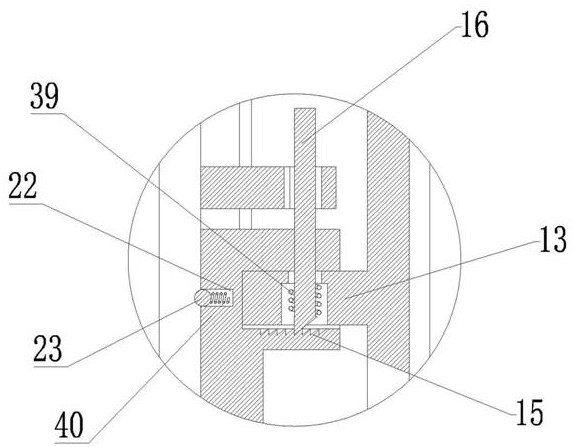
[0027] Embodiment 2, on the basis of Embodiment 1, a plurality of cylindrical grooves 22 are distributed on the inner wall of the second cylinder 11, the axes of the cylindrical grooves 22 are arranged radially along the second cylinder 11, and the cylindrical grooves 22 are slidably connected with The positioning glass bead 23, the fifth spring 41 is connected between the bottom wall of the cylindrical groove 22 and the positioning glass bead 23, and the fifth spring 41 gives the positioning wave bead a thrust toward the axis of the first cylinder 2, and the first cylinder 2 An annular groove is provided on the outer wall, and one end of the positioning glass bead 23 is placed in the annular groove, and the other end of the positioning glass bead 23 is placed in the cylindrical groove 22. When the first cylinder 2 passes through the second cylinder 11 and moves to the second When the outer wall of the first cylinder 2 is in contact with the positioning glass bead 23, the posit...

Embodiment 3

[0028] Embodiment 3, on the basis of Embodiment 1, a plurality of pulp outlets 24 are hinged on the lower end of the outer wall of the screw rod 1, and the plurality of pulp outlets 24 correspond to a plurality of pulp outlets one by one, and the screw rod 1 and the pulp outlet The door 24 is connected by a torsion spring, and the pulp outlet 24 is used in conjunction with the pulp outlet. In the initial state, the pulp outlet 24 is in sealing contact with the pulp outlet under the action of the torsion spring. The slurry opening is blocked by the crushed rocks drilled, and when the high-pressure grouting is performed, the slurry outlet door 24 is opened under the pressure of the high-pressure slurry, and the slurry can flow out from the slurry outlet.


PUM


Abstract

The invention relates to a coal mine goaf treatment and collapse backfill slurrying and grouting device. The device aims to solve the problems that in the coal mine goaf treatment process in the prior art, the working efficiency is low, the labor intensity of workers is high, and slurry flows out and the hole sealing difficulty is high due to the fact that a grouting opening cannot be sealed in time after grouting is finished. A screw rod is supported by a drilling machine for drilling, drilling is automatically sealed without pulling out the screw rod, a stop-grouting plug and a sealing rubber plug after drilling is finished, a grouting pump switch is directly turned on, high-pressure grouting is conducted on a grouting hole, after grouting is finished, the screw rod is separated from the sealing rubber plug under the action of the drilling machine, and the sealing rubber plug is left in the grouting hole under the support of a second barrel and an arc-shaped plate to continuously seal the grouting hole. The device is easy to operate, the operation space of workers during goaf treatment is saved, the working efficiency is improved, meanwhile, the labor intensity of the workers is reduced, and the problems that grout flows back after grouting, and hole sealing is difficult are effectively solved.

Description

technical field [0001] The invention relates to the technical field of coal mine goaf filling equipment, and more specifically relates to a coal mine goaf treatment and collapse backfill grouting and grouting device. Background technique [0002] In the goaf that is usually left in the process of coal mining in coal mines, there is a thicker direct roof above the working face of the goaf under the coal mine. The direct roof mainly has a large thickness of rock formation, low strength of the rock formation, and high degree of fracture development. , Poor integrity, low self-stabilization ability, etc., cause the roof of the working face and the roof of the roadway to fall and collapse easily during the mining process. will get bigger and bigger. In order to prevent leakage accidents of the broken roof, it is necessary to control in advance before the partial roof leakage occurs. The previous technology mainly adopts strengthening geological exploration, strengthening constru...

Claims


Application Information

Patent Timeline
Patent Type & Authority Applications(China)
IPC IPC(8): E21F15/08E21B17/22
CPCE21F15/08E21B17/22
Inventor 丁陈建何宝林李志永熊彩霞张立合史继彪张建国
Owner 徐州中矿岩土技术股份有限公司
Learn More