Top-mounted ball valve and assembling tool and process of top-mounted ball valve

A technology for assembling tools and ball valves, which is used in hand-held tools, manufacturing tools, valve devices, etc., can solve the problems of troublesome installation, damage to the soft sealing surface of the valve seat, and difficult processing, and meets the requirements of convenient assembly and disassembly and matching accuracy. Low, reliable assembly quality effect

Pending Publication Date: 2021-06-22
ZHEJIANG BETHEL TECH CO LTD
View PDF0 Cites 5 Cited by
  • Summary
  • Abstract
  • Description
  • Claims
  • Application Information

AI Technical Summary

Problems solved by technology

The metal seat of the threaded seat structure is installed in the valve body through the threaded ring. In cryogenic conditions, the metal seat and the threaded ring must be made of austenitic stainless steel. Austenitic stainless steel has the characteristics of low hardness and high toughness. When assembling, the valve seat is first retracted into the passages on both sides of the valve cavity by rotating the threaded ring, and the ball is loaded into the valve cavity, and then the threaded ring is reversely rotated to press the valve seat to the ball; the disadvantages are: metal valve seat and The threaded ring is made of the same material, and the two threads are easy to bite during assembly, so it is difficult to reliably tighten the thread in place. During the tightening process, uneven force will squeeze, deform and damage the thread teeth, and even drop iron filings to damage the valve seat Soft sealing surface; moreover, the threaded valve seat requires high machining accuracy, precise and suitable clearance and tolerance matching requirements, and difficult processing, especially not suitable for large-diameter cryogenic ball valves
The hinge of the hinge valve seat structure is made of multi-section arc splicing, which is cumbersome to manufacture and troublesome to install, and there is a hidden danger of the hinge joint falling off during use, and the reliability is poor

Method used


Image

  • Top-mounted ball valve and assembling tool and process of top-mounted ball valve
  • Top-mounted ball valve and assembling tool and process of top-mounted ball valve
  • Top-mounted ball valve and assembling tool and process of top-mounted ball valve

Examples


Embodiment Construction

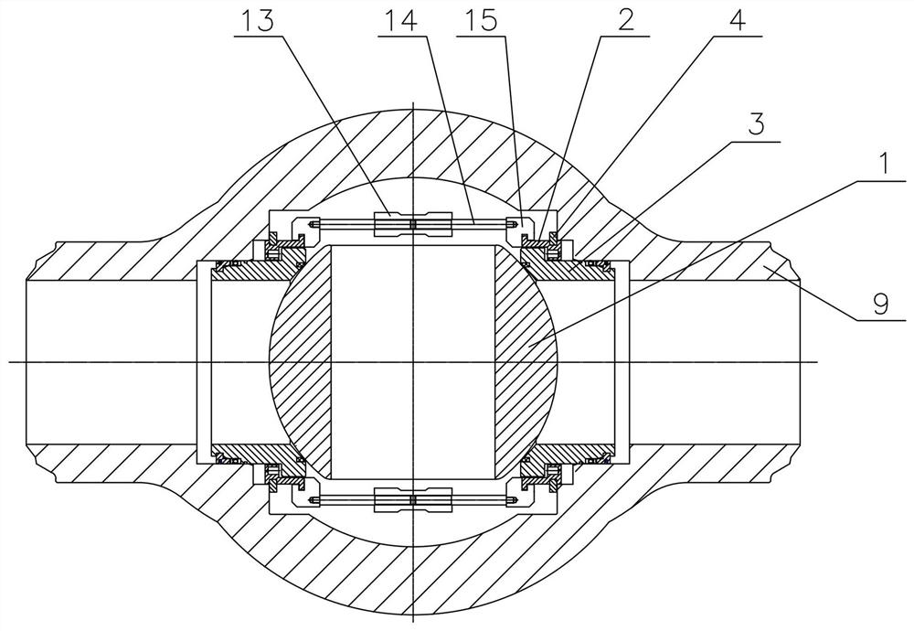
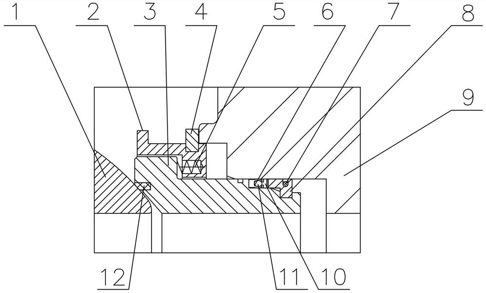
[0022] Such as figure 1 , figure 2 The top entry ball valve shown includes a valve body 9, a ball 1, and a valve seat 3. A rubber sealing ring 12 is embedded in the sealing surface of the valve seat 3 and cooperates with the ball 1 to form a soft seal pair. The valve seat 3 is from the end close to the ball 1 to the The outer circular surface at one end away from the sphere 1 has the first outer cylindrical surface, the second outer cylindrical surface, and the third outer cylindrical surface whose diameter gradually decreases, and the valve body 9 is made in the channel from the side of the valve cavity to the side away from the valve cavity. There are a first cylindrical cavity and a second cylindrical cavity with gradually decreasing inner diameters, and the dynamic sealing fit between the second outer cylindrical surface of the valve seat 3 and the inner wall of the second cylindrical cavity of the valve body 9 makes the second outer cylindrical cavity of the valve seat 3...


PUM


Abstract

The invention relates to a top-mounted ball valve and an assembling tool and process of the top-mounted ball valve. The top-mounted ball valve structurally comprises a valve body, a ball body and a valve seat. The valve seat is installed in an inlet and outlet channel of the valve body through a spring seat and a clamping spring by means of the special assembling tool, and the problem that threads are prone to being damaged due to the fact that the valve seat is driven through the threads in the prior art is solved. The requirement for the matching precision between the valve seat and the spring seat is low, parts are easy to machine, assembling and disassembling are convenient, and the assembling quality is reliable.

Description

technical field [0001] The invention belongs to the field of valves, in particular to a top-mounted cryogenic ball valve. The invention is applicable to working conditions of cryogenic medium such as liquid nitrogen and liquid oxygen at -196°C. Background technique [0002] At present, top-entry cryogenic ball valves at home and abroad mostly adopt threaded seat structure or hinged seat structure. The metal seat of the threaded seat structure is installed in the valve body through the threaded ring. In cryogenic conditions, the metal seat and the threaded ring must be made of austenitic stainless steel. Austenitic stainless steel has the characteristics of low hardness and high toughness. When assembling, the valve seat is first retracted into the passages on both sides of the valve cavity by rotating the threaded ring, and the ball is loaded into the valve cavity, and then the threaded ring is reversely rotated to press the valve seat to the ball; the disadvantages are: me...

Claims


Application Information

Patent Timeline
Patent Type & Authority Applications(China)
IPC IPC(8): F16K5/06F16K5/20B25B27/24
CPCB25B27/24F16K5/0626F16K5/0663F16K5/201
Inventor 尚玉来金瑞建金卡迪吕智健李平林光办谷尚铸
Owner ZHEJIANG BETHEL TECH CO LTD
Why Eureka
Try Eureka