Preparation method of double-sided micro-channel flat pulsating heat pipe and application thereof to high-power chip heat dissipation device

A pulsating heat pipe and chip heat dissipation technology, applied in lighting and heating equipment, indirect heat exchangers, electrical components, etc., can solve the problems of insufficient heat transfer of heating elements, insufficient space compactness, narrow and long conduit connections, etc. Achieve the effect of strengthening environmental adaptability, improving heat transfer limit, and simple processing and manufacturing process

Inactive Publication Date: 2021-06-22
JIANGSU UNIV
View PDF9 Cites 1 Cited by
  • Summary
  • Abstract
  • Description
  • Claims
  • Application Information

AI Technical Summary

Problems solved by technology

Patent CN110958822A discloses a loop heat pipe system for servers. The heat is transported to the condenser through the plate evaporator through the conduit. In this design, the conduit connection is narrow and long, accompanied by heat loss, which leads to the failure of the heat generated by the heating element. It is fully transported to the condenser, and the design space is not compact, and the volume is large, and it is mostly used for heat dissipation in server systems with small power

Method used


Image

  • Preparation method of double-sided micro-channel flat pulsating heat pipe and application thereof to high-power chip heat dissipation device
  • Preparation method of double-sided micro-channel flat pulsating heat pipe and application thereof to high-power chip heat dissipation device
  • Preparation method of double-sided micro-channel flat pulsating heat pipe and application thereof to high-power chip heat dissipation device

Examples


Embodiment Construction

[0030] In order to make the object, technical solution and advantages of the present invention clearer, the present invention will be further described in detail below in conjunction with the accompanying drawings and embodiments. It should be understood that the specific embodiments described here are only used to explain the present invention, not to limit the present invention.

[0031] In order to make the technical solutions and advantages of the present invention clearer, the present invention will be further described in detail below in conjunction with specific implementation cases. The specific embodiments described here are only used to explain the present invention, not to limit the present invention.

[0032] The materials and reagents used in the examples of the present invention are commercially available unless otherwise specified.

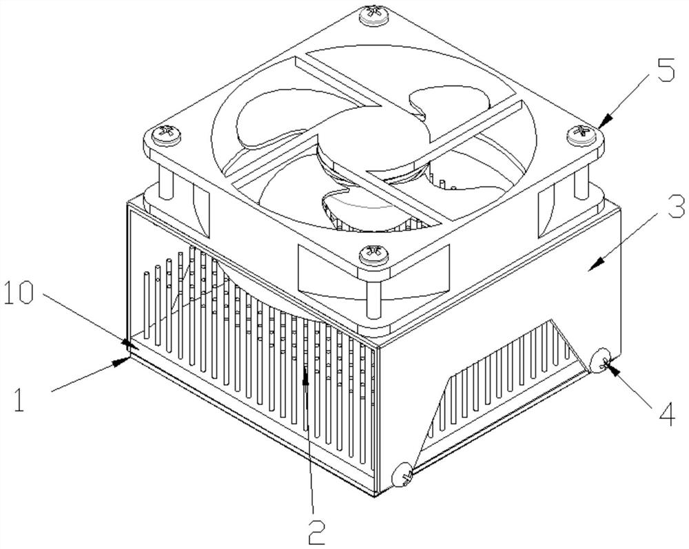
[0033] Such as Figure 1-2 As shown, a high-power chip cooling device based on a double-sided microchannel flat plate pulsating ...


PUM

PropertyMeasurementUnit
particle diameteraaaaaaaaaa
thicknessaaaaaaaaaa
heightaaaaaaaaaa

Abstract

The invention discloses a preparation method of a double-sided micro-channel flat plate pulsating heat pipe and application of the double-sided micro-channel flat plate pulsating heat pipe to a high-power chip heat dissipation device. The device comprises a method for preparing the double-sided micro-channel flat plate pulsating heat pipe, the two opposite surfaces of the double-sided micro-channel flat plate pulsating heat pipe are an evaporation end face and a condensation end face respectively, the evaporation end face and the condensation end face are both provided with identical micro-channels, the micro-channels on the two surfaces are communicated with each other, and the double-face micro-channel flat plate pulsating heat pipe is filled with working media in a sealed mode; a heat dissipation unit is fixedly connected to the upper portion of the evaporation end face of the double-face micro-channel flat plate pulsating heat pipe; and the chip is fixedly installed on the evaporation end face, and heat dissipation of the chip is achieved through circulation of a working medium on the evaporation end face and the condensation end face.

Description

technical field [0001] The invention belongs to the technical field of electronic devices and electronic device cooling, and in particular relates to a preparation method of a double-sided microchannel flat plate pulsating heat pipe and its application to a high-power chip cooling device. Background technique [0002] With the development of the electronics industry toward miniaturization, high power, and high integration, the heat dissipation of electronic components is facing important challenges. Traditional heat dissipation technology can no longer meet the development needs of high-power, high-heat-flux electronic components. The heat generation problem has seriously restricted the development of high-precision electronic components such as computer chips. It is important to develop energy-saving and efficient heat dissipation technology and heat dissipation devices. and application value. Due to its excellent heat transfer performance, simple structure, and low proces...

Claims


Application Information

Patent Timeline
Patent Type & Authority Applications(China)
IPC IPC(8): F28D15/02F28D15/04H01L23/427H01L23/44B23P15/00
CPCF28D15/02F28D15/046H01L23/427H01L23/445B23P15/00F28D2015/0225
Inventor 王海赵鑫黄菊王军锋
Owner JIANGSU UNIV
Why Eureka
Try Eureka