Drilling and coring device for early-age concrete

A concrete and early-age technology, which is applied in the field of drilling and coring devices for early-age concrete, can solve the problems of low success rate, broken cores, missing corners, and slow one-way coring efficiency, etc. Effect of large chip removal space

Inactive Publication Date: 2021-06-22
ANHUI UNIV OF SCI & TECH
View PDF12 Cites 2 Cited by
  • Summary
  • Abstract
  • Description
  • Claims
  • Application Information

AI Technical Summary

Problems solved by technology

[0007] The patent of the present invention provides a drilling and coring device for early-age concrete, which improves the problems of broken cores and missing corners in the core samples obtained by the existing coring method, and solves the problems of early-age concrete. The problems of low success rate and slow one-way coring efficiency in the process of concrete coring can be used for coring processing of common 100mm×100mm×100mm and 150mm×150mm×150mm cubic concrete in the laboratory, with accurate positioning and fast sampling , Rapid chip removal, small friction between the inner wall of the coring device and the core sample

Method used


Image

  • Drilling and coring device for early-age concrete
  • Drilling and coring device for early-age concrete
  • Drilling and coring device for early-age concrete

Examples


Embodiment 1

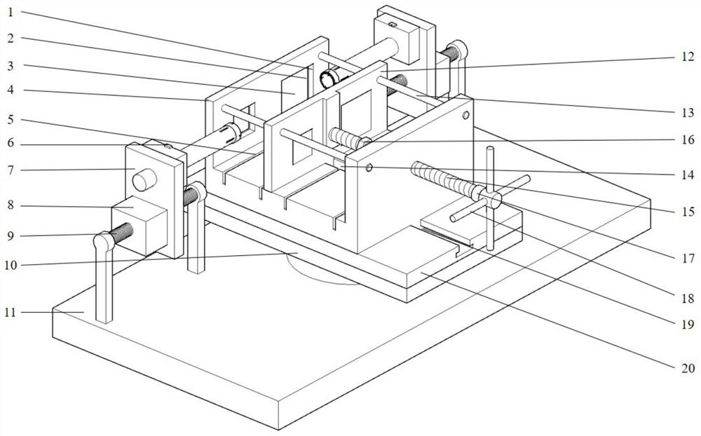
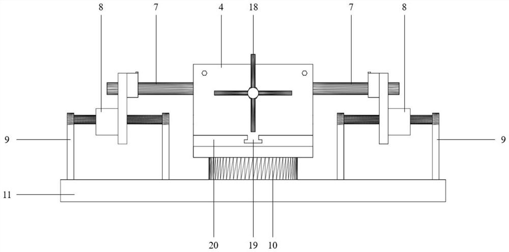
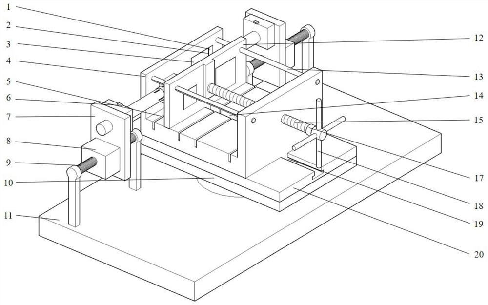
[0031] Such as figure 1 A drilling core device for early concrete is a positioning recess 1, a measuring probe fixing groove 2, a fixed support 4, a drain groove 5, a core drill device 7, a motor 8, a thread The fixing assembly 9, the hydraulic jack 10, the base 11, the moving fixing plate 12, the auxiliary positioning rod 13, the slide 14, the propulsion screw 15, nut 16, electronic torque measuring meter 17, torque measuring handle 18, T-shaped body 19, T-shaped The slot plate 20 is composed, the fixed support 4, the movable fixing plate 12, the auxiliary positioning rod 13 is connected to each other, and the nut 16 is connected to the propulsion screw 15, the propulsion screw 15 is used to connect the moving fixing plate. 12, fixed support 4 and electronic torque measuring meter 17, the electronic torque measuring meter 17 is connected to the torque measuring handle 18, the propulsion screw 15, nut 16, electronic torque measuring meter 17, torque measuring handle 18 interconnec...

Embodiment 2

[0039] Such as figure 1 A drilling core device for early concrete is a positioning recess 1, a measuring probe fixing groove 2, a fixed support 4, a drain groove 5, a core drill device 7, a motor 8, a thread The fixing assembly 9, the hydraulic jack 10, the base 11, the moving fixing plate 12, the auxiliary positioning rod 13, the slide 14, the propulsion screw 15, nut 16, electronic torque measuring meter 17, torque measuring handle 18, T-shaped body 19, T-shaped The slot plate 20 is composed, the fixed support 4, the movable fixing plate 12, the auxiliary positioning rod 13 is connected to each other, and the nut 16 is connected to the propulsion screw 15, the propulsion screw 15 is used to connect the moving fixing plate. 12, fixed support 4 and electronic torque measuring meter 17, the electronic torque measuring meter 17 is connected to the torque measuring handle 18, the propulsion screw 15, nut 16, electronic torque measuring meter 17, torque measuring handle 18 interconnec...


PUM


Abstract

The invention relates to a drilling and coring device for early-age concrete. The device is composed of a positioning groove, a wave velocity measuring probe, a fixed support, a drainage tank, a laser range finder, a coring drill bit device, a motor, a thread fixing assembly, a hydraulic jack, a base, a movable fixing plate, an auxiliary positioning rod, a propelling screw, an electronic torque measuring meter, a torque measuring meter handle, a T-shaped sliding groove plate, a notch, a chip removal opening and carborundum particles. According to the wave velocity condition of the cubic sample measured by the wave velocity measuring probe, the sample is subjected to stage treatment under different wave velocity levels, so that double-end-face coring is realized, and the coring efficiency is greatly improved; the coring bit device is subjected to nickel plating treatment, the bit part is provided with the chip removal opening, and the notch part is electroplated with carborundum, so that a larger chip removal space is provided in the early-age concrete drilling and coring process, and the problems are solved that the internal cementing capacity of the early-age concrete is poor, the gelation structure strength is low, and the friction force between the inner wall of the drill bit and the core sample is too large, so that the core sample is broken and has unfilled corner.

Description

Technical field [0001] The present invention belongs to the field of drilling core processing technology, and more particularly to a drilling core apparatus for early concrete. Background technique [0002] When the early concrete penetration test is carried out on a conventional three-axis test machine with an osmotic device, since the test instrument equipment requires the size of the test piece to be φ50 × 100 mm cylinder. However, φ50 × 100 mm cylindrical test piece is not easy to obtain directly by pouring, so the laboratory is usually based on the 90mm × 150mm × 150 mm cube test piece by a series of finishing, and the finger is performed to obtain a cylinder. Specimen. [0003] Since the current laboratory is not specifically used for the concrete core, it is usually used in the concrete cube test piece, which is the existing rock core core, and the core method is to use the clamp to clamp the cube test piece. The end diagonal is fixed, and the inner structure is fragile du...

Claims


Application Information

Patent Timeline
Patent Type & Authority Applications(China)
IPC IPC(8): G01N1/08G01N29/07G01L5/00G01B11/02
CPCG01N1/08G01N29/07G01L5/0042G01B11/02
Inventor 薛维培高聪徐威申磊张瀚文范红君
Owner ANHUI UNIV OF SCI & TECH
Why Eureka
Try Eureka