5G antenna and 5G antenna mounting base

A mount and antenna technology, applied in the field of 5G antennas, can solve the problems of unusable 5G antenna mounts and achieve the effects of safe use, accurate angle positioning, and enhanced structural strength

Inactive Publication Date: 2021-06-22
SHENZHEN SHUNDACHENG TECH CO LTD
View PDF0 Cites 0 Cited by
  • Summary
  • Abstract
  • Description
  • Claims
  • Application Information

AI Technical Summary

Problems solved by technology

[0004] When installing the 5G antenna, the bottom of the 5G antenna needs to be fixed firmly. Most of the existing 5G antenna mounts use welding to install the 5G antenna on the 5G antenna mount. When the 5G antenna mount is partially rotten and damaged, it needs to be completely removed. , causing the entire 5G antenna mount to be unusable, a detachable 5G antenna mount is needed to meet people's needs

Method used


Image

  • 5G antenna and 5G antenna mounting base
  • 5G antenna and 5G antenna mounting base
  • 5G antenna and 5G antenna mounting base

Examples


Embodiment 1

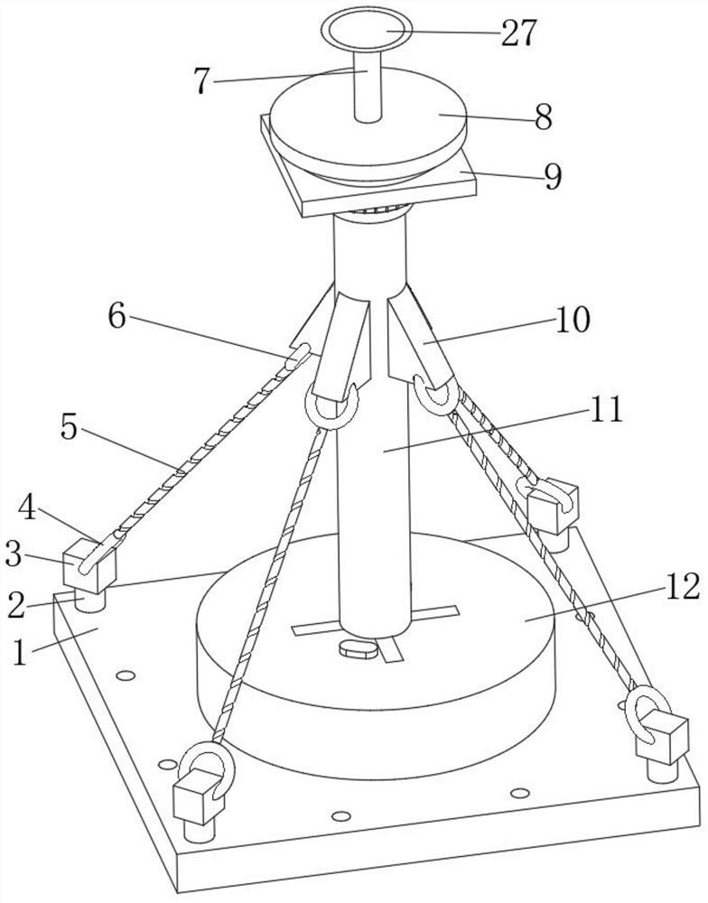
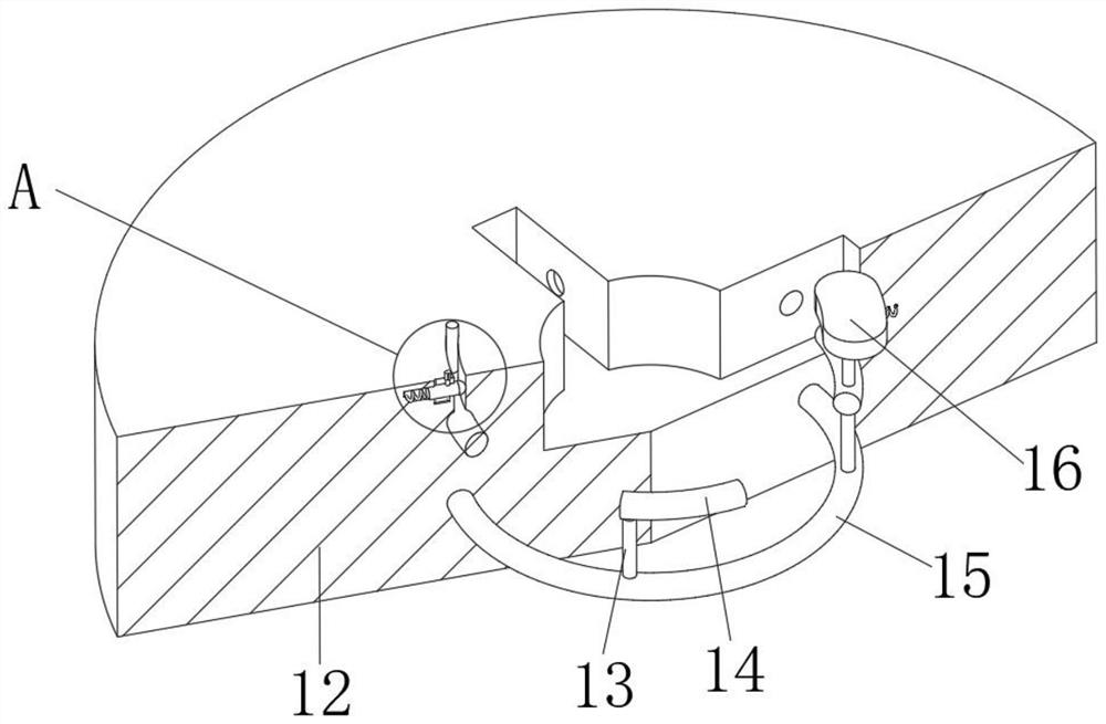
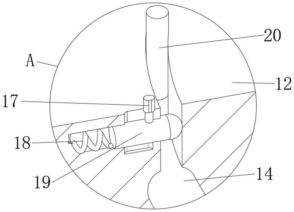
[0031] refer to Figure 1-5 , a 5G antenna and a 5G antenna mounting seat, including a bottom plate 1 and a support column 11, the top outer wall of the bottom plate 1 is fixed with a mounting seat 12 by screws, and the top outer wall of the mounting seat 12 is provided with a first circular groove, the mounting seat 12 The outer wall of the top of the first circular groove has a first rectangular groove on the inner wall, and the inner wall of the first rectangular groove has a first annular groove, and the inside of the mounting base 12 has a second annular groove, and the second annular groove The peripheral outer wall is fixedly installed with four second mounting rods 13 equidistantly distributed, and the top of the second mounting rods 13 is fixedly mounted with a first movable rod 14, and the first movable rod 14 is adapted to the first annular groove, wherein the symmetrical The circumferential outer walls of the two first movable rods 14 are fixedly equipped with push...

Embodiment 2

[0042] refer to Figure 5 , a 5G antenna and a 5G antenna mount. Compared with Embodiment 1, this embodiment also includes a water guide plate 26 fixed by screws on the top of the first mounting plate 8 located on the outer peripheral wall of the first mounting rod 7 .

[0043] Working principle: the water guide plate 26 is installed on the outer peripheral wall of the first installation rod 7, and is closely connected with the outer peripheral wall of the first installation rod 7, which enhances the structural stability of the first installation rod 7, and at the same time, can prevent rainwater The joint between a mounting rod 7 and the first mounting disc 8 accumulates, causing the bottom of the first mounting rod 7 to rot, prolonging the service life of the device.


PUM


Abstract

The invention belongs to the technical field of 5G antennas, particularly relates to a 5G antenna and a 5G antenna mounting base, and aims to solve the problem that the 5G antenna is inconvenient to replace, disassemble and assemble. The 5G antenna mounting base comprises a bottom plate and a supporting column, the mounting base is fixed to the outer wall of the top of the bottom plate, and a first circular groove is formed in the outer wall of the top of the mounting base; a first rectangular groove is formed in the position, located on the inner wall of the first circular groove, of the outer wall of the top of the mounting base, a first annular groove is formed in the inner wall of the first rectangular groove, a second annular groove is formed in the mounting base, and four second mounting rods distributed at equal intervals are fixedly mounted on the circumferential outer wall of the second annular groove; and a first movable rod is fixedly mounted at the top end of the second mounting rod. The supporting column and the first fixing plate are inserted into the first circular groove and the first rectangular groove in the top of the mounting base, the push rod is pushed to enable the first movable rod to rotate, the first movable rod is rotationally inserted into the third annular groove, the supporting column and the first fixing plate are fixed tightly, and workers can conveniently disassemble, assemble and use the 5G antenna mounting base.

Description

technical field [0001] The invention relates to the technical field of 5G antennas, in particular to a 5G antenna and a 5G antenna mount. Background technique [0002] In the 5G (fifth-generation mobile communication) era of the Internet of Everything, smart cities, unmanned driving, unmanned factories, remote surgery--5G Capriccio is becoming clearer. The blueprint for the 5G network is a high rate 100 times that of 4G, which will reach 10Gbit / s, a low latency of less than 1ms, a high density supporting more than 100 billion connections, and a high capacity 1000 times that of 4G. On the one hand, antenna systems such as massive MIMO (massive array antenna technology) antennas and integrated active antennas are required to serve macro base stations. On the other hand, ubiquitous micro base stations require high integration of antennas and base station equipment. [0003] With the continuous development of mobile communication from 2G, 3G, 4G to 5G, mobile communication ante...

Claims


Application Information

Patent Timeline
Patent Type & Authority Applications(China)
IPC IPC(8): H01Q1/12
CPCH01Q1/12
Inventor 陈华明
Owner SHENZHEN SHUNDACHENG TECH CO LTD
Why Eureka
Try Eureka