
Alternating current excitation transformation method and system of grid-connected direct current excitation synchronous generator set

A technology of synchronous generator and AC excitation, which is applied in the direction of synchronous generators, manufacturing motor generators, electric components, etc. It can solve the problems of deteriorating working conditions of generator sets, reduced efficiency, and affecting the safe operation of generator sets, so as to improve operating efficiency , small changes, simple and easy technical means

Pending Publication Date: 2021-06-22
广州华南鑫沨能源科技有限公司
View PDF0 Cites 0 Cited by
  • Summary
  • Abstract
  • Description
  • Claims
  • Application Information

AI Technical Summary

Problems solved by technology

Due to the constraints of grid frequency and grid operation conditions, the prime movers driving these synchronous generators have been running at synchronous speed and cannot always be at the optimal speed, which leads to the deterioration of the working conditions of the generator set and the reduction of efficiency, which affects the generator set. safe operation of

Method used


Image

  • Alternating current excitation transformation method and system of grid-connected direct current excitation synchronous generator set
  • Alternating current excitation transformation method and system of grid-connected direct current excitation synchronous generator set

Examples


Embodiment

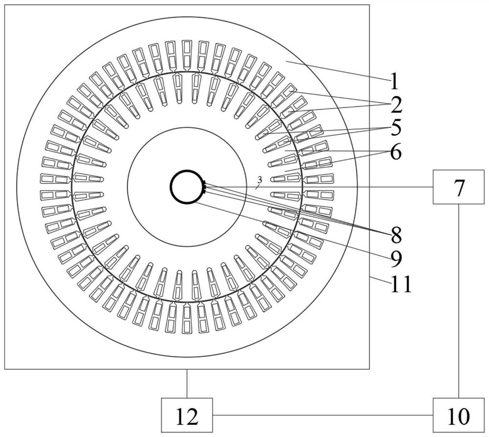
[0034] The AC excitation transformation system of the grid-connected DC excitation synchronous generator set, such as figure 2 As shown, it includes a DC excitation synchronous generator, a rotor AC winding 5, a rotor core 6, an AC-DC bidirectional converter 7, a brush 8, a slip ring 9, a measurement control system 10, a prime mover and its transmission mechanism 12;

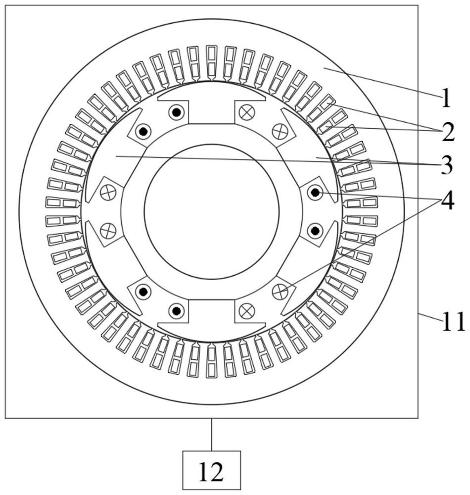
[0035] The stator winding 2 of the DC excitation synchronous generator is connected to the AC power grid; the rotor core 6 and the rotor AC winding 5 are installed at the positions of the pole core 3 and the DC excitation winding 4 on the main magnetic pole of the DC excitation synchronous generator rotor before transformation, The rotor AC winding 5 is installed in the rotor iron core 6 slot; the rotor AC winding 5 is connected with the AC-DC bidirectional converter 7 through the brush 8 and the slip ring 9; Component 11 remains unchanged.

[0036] The AC-DC-AC bidirectional converter 7 provides AC excitation...


PUM


Abstract

The invention discloses an alternating current excitation transformation method and system of a grid-connected direct current excitation synchronous generator set. The system comprises a direct current excitation synchronous generator, a rotor alternating current winding, a rotor iron core, an alternating current-direct current-alternating current bidirectional converter, an electric brush, a slip ring, a measurement control system, a prime motor and a transmission mechanism of the prime motor. Most equipment and parts of an original synchronous power generation system are reserved, only the rotor main magnetic poles of the original synchronous power generation set are replaced by the rotor alternating current windings and the rotor iron cores with the same number of poles as the stator windings, the original system is slightly modified, and the modification cost is low. The technical means is simple and easy to implement, when the rotor operates at different rotating speeds, the rotating magnetic field rotating speed on the rotor is consistent with the rotating magnetic field rotating speed of the stator by controlling alternating current exciting current parameters, then the operating efficiency of a prime motor and a whole power generation system is improved, and the operating condition of an original synchronous generator set is improved; the operation stability of the generator set is improved.

Description

technical field [0001] The invention relates to the fields of DC excitation and AC excitation power generation, in particular to an AC excitation modification method and system for a grid-connected DC excitation synchronous generator set. Background technique [0002] Synchronous generator sets have been widely used in energy development such as hydroelectric power generation, wind power generation, and thermal power generation due to their advantages of large capacity, adjustable active power and reactive power. Due to the constraints of grid frequency and grid operation conditions, the prime movers driving these synchronous generators have been running at synchronous speed and cannot always be at the optimal speed, which leads to the deterioration of the working conditions of the generator set and the reduction of efficiency, which affects the generator set. safe operation. [0003] With the development of current energy development, in order to improve the energy convers...

Claims


Application Information

Patent Timeline
IPC IPC(8): H02J3/38H02K19/26H02K13/00H02K11/04H02K15/00H02K15/02
CPCH02J3/381H02K19/26H02K13/003H02K11/04H02K15/0006H02K15/02
Inventor 谢宝忠
Owner 广州华南鑫沨能源科技有限公司
Learn More