Positioning and cutting-off protection equipment for steel material machining

A technology for material processing and protection equipment, applied in metal processing equipment, shearing machine equipment, metal processing machinery parts, etc., can solve the problems of reducing the service life of the blade, damage to the arm of the porter, and reducing the aesthetics of the cutting surface, etc., to achieve increased The effect of increasing the service life, increasing the protection range, and reducing the phenomenon of knife vibration

Inactive Publication Date: 2021-06-25
王英
View PDF0 Cites 0 Cited by
  • Summary
  • Abstract
  • Description
  • Claims
  • Application Information

AI Technical Summary

Problems solved by technology

[0004] (1) During the cutting process, due to the vibration of the cutting edge, the cutting surface will appear vibrating, which are some water wave-like patterns. These patterns will first reduce the aesthetics of the cutting surface, and second will make the cutting The unevenness of the surface is not conducive to later reprocessing. The third pair of blades will cause a lot of wear, damage the blades, reduce the service life of the blades, waste time to replace the blades, and reduce the working efficiency of the device.
[0005] (2) There will be a lot of metal sparks during the cutting process. These metal sparks will splash on the operator's body, causing the danger of burns, and there is a great safety hazard. If these metal sparks are not collected in time, they will pollute the work. environment, resulting in difficulties in later collection and the disadvantages of reducing the environmental protection of the device
[0006] (3) The current loading of steel pipes is generally carried by hand, which requires a lot of manpower and time, which will not only reduce the working efficiency of the device, but also cause potential safety hazards to injure the porters during the handling process. The process of loading materials is extremely cumbersome, sometimes because the weight of the steel pipe is too large, the arms of the porters are permanently damaged, which is not conducive to the long-term development of production
[0007] (4) During the feeding process of the steel pipe feeder, due to the heavy weight of the steel pipe, the universal wheel is damaged and the service life of the universal wheel is reduced, thereby reducing the service life of the steel pipe feeder and reducing the upper Availability of the feeding device

Method used


Image

  • Positioning and cutting-off protection equipment for steel material machining
  • Positioning and cutting-off protection equipment for steel material machining
  • Positioning and cutting-off protection equipment for steel material machining

Examples


Embodiment Construction

[0033] The following will clearly and completely describe the technical solutions in the embodiments of the present invention with reference to the accompanying drawings in the embodiments of the present invention. Obviously, the described embodiments are only some, not all, embodiments of the present invention. Based on the embodiments of the present invention, all other embodiments obtained by persons of ordinary skill in the art without making creative efforts belong to the protection scope of the present invention.

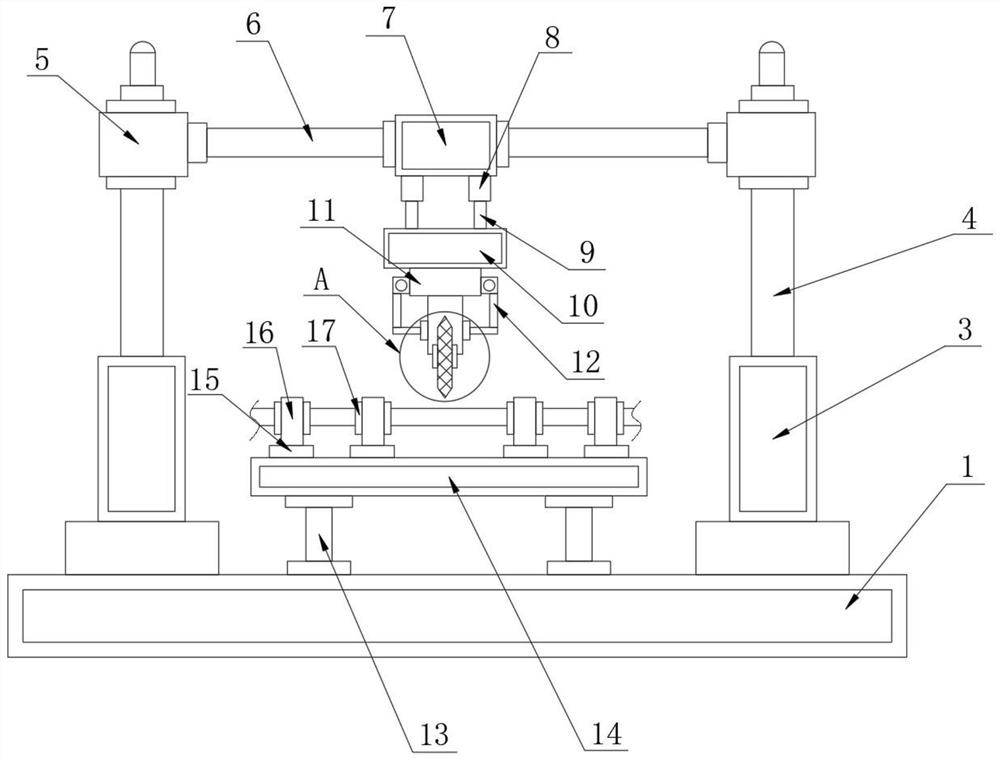
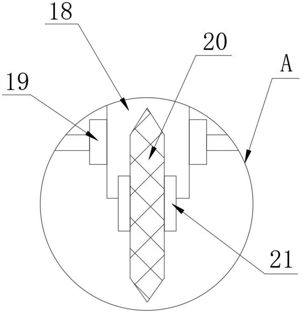
[0034] as attached Figure 1-9 The shown one is based on the positioning and cutting protection equipment for steel material processing, including a steel pipe cutting machine 1, a steel pipe feeding machine 2, and a lifting control column 3 is fixedly installed on the top of one side of the steel pipe cutting machine 1, and the lifting control column 3. The top of one side is detachably mounted with a lifting sliding column 4, and the top of one side of the l...


PUM


Abstract

The invention discloses positioning and cutting-off protection equipment for steel material machining, and particularly relates to the field of machining. The positioning and cutting-off protection equipment comprises a steel pipe cutting-off machine and a steel pipe feeding machine, a lifting control column is fixedly mounted at the top end of one side of the steel pipe cutting-off machine, and a lifting sliding column is detachably mounted at the top end of one side of the lifting control column; a lifting sliding block is detachably mounted at the top end of one side of the lifting sliding column, a sliding rod is detachably mounted on one side of the lifting sliding block, a horizontal sliding block is slidably connected to one side of the sliding rod, a shrinking column is detachably mounted at the bottom end of one side of the horizontal sliding block, and a telescopic rod is detachably mounted at the bottom end of one side of the shrinking column; and a multi-linkage disc is detachably mounted on one side of the telescopic column. Through cooperation of a mounting column, a cutting edge and a shockproof dismounting ring, the cutter vibration phenomenon of the cutting edge in the cutting process is prevented, the effect that the cutting surface is smoother is achieved, and the problem that due to cutter vibration, uneven patterns appear on the cutting surface, and later steel pipe remachining is affected is solved.

Description

technical field [0001] The invention relates to the technical field of mechanical processing, more specifically, the invention relates to a positioning and cutting protection device based on steel material processing. Background technique [0002] In many construction industries, large steel pipes are needed. In the process of steel pipe production, the steel pipes produced are of uneven length, so in order to get the steel pipes of the length we need, we need to use a cutting machine to cut the steel pipes Now the cutting device generally used is the grinding wheel cutting device. Although the cutting surface of the grinding wheel cutting device is relatively flat, as people's demand for products becomes more and more perfect, they pay great attention to the protective measures during the cutting process. First, it can reduce the wear and tear of the device, and second, it can improve the safety of the device and reduce the existing safety hazards, so as to better improve t...

Claims


Application Information

Patent Timeline
IPC IPC(8): B23D21/00B23D33/00B23D33/02B23Q11/00B23Q11/08
CPCB23D21/00B23D33/00B23D33/02B23Q11/00B23Q11/0046B23Q11/08
Inventor 王英
Owner 王英
Why Eureka
Try Eureka