
Automatic laser cutting device and method for long and thin pipes

A laser cutting, slender tube technology, applied in laser welding equipment, welding equipment, metal processing equipment and other directions, can solve the problems of pipe damage, low cutting efficiency, troublesome operation, etc., to ensure cutting accuracy, position stability, improve cutting The effect of efficiency

Pending Publication Date: 2021-06-25
江西晖旭实业有限公司
View PDF11 Cites 1 Cited by
  • Summary
  • Abstract
  • Description
  • Claims
  • Application Information

AI Technical Summary

Problems solved by technology

[0003] The existing automatic laser cutting device for slender pipes has low cutting efficiency. It is troublesome to cut pipes of different thicknesses, and the cutting efficiency is low. During the cutting process, as the distance between the laser cutting components and the cutting depth gradually increases, the cutting efficiency is not At the same time, the cut pipe falls after cutting, which is easy to damage the pipe assembly. For this reason, we propose an automatic laser cutting device for slender pipes.

Method used


Image

  • Automatic laser cutting device and method for long and thin pipes
  • Automatic laser cutting device and method for long and thin pipes
  • Automatic laser cutting device and method for long and thin pipes

Examples


Embodiment Construction

[0024] The following will clearly and completely describe the technical solutions in the embodiments of the present invention with reference to the accompanying drawings in the embodiments of the present invention. Obviously, the described embodiments are only some, not all, embodiments of the present invention.

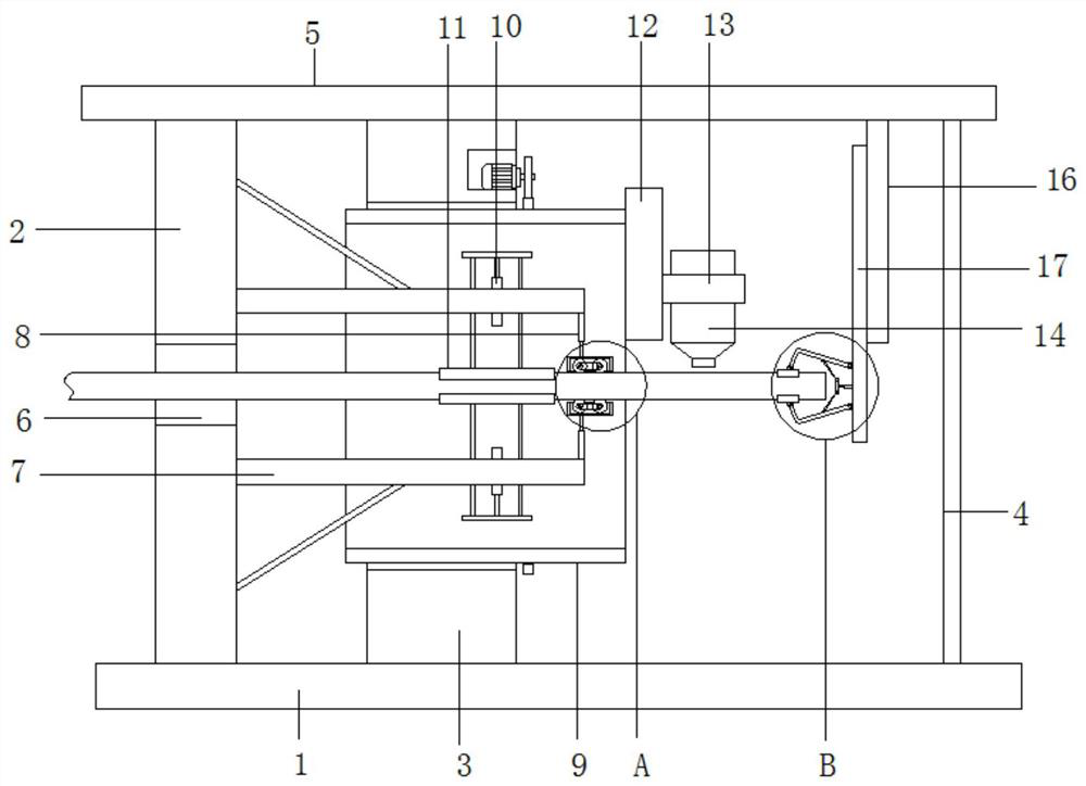
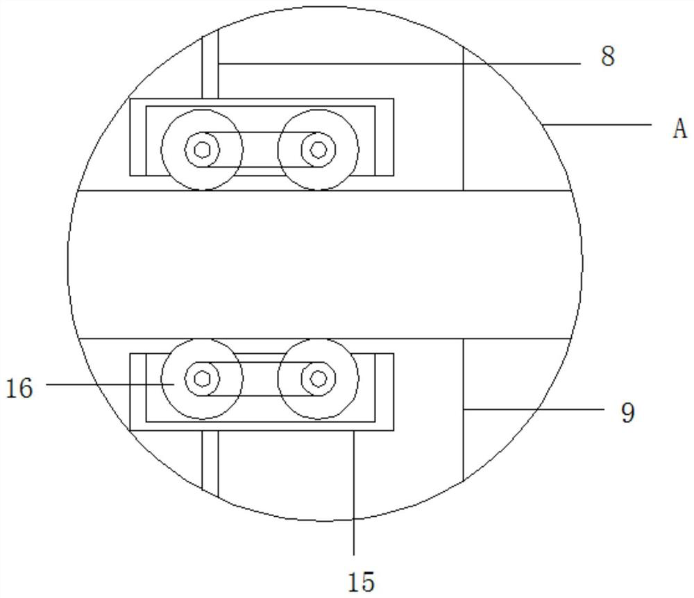
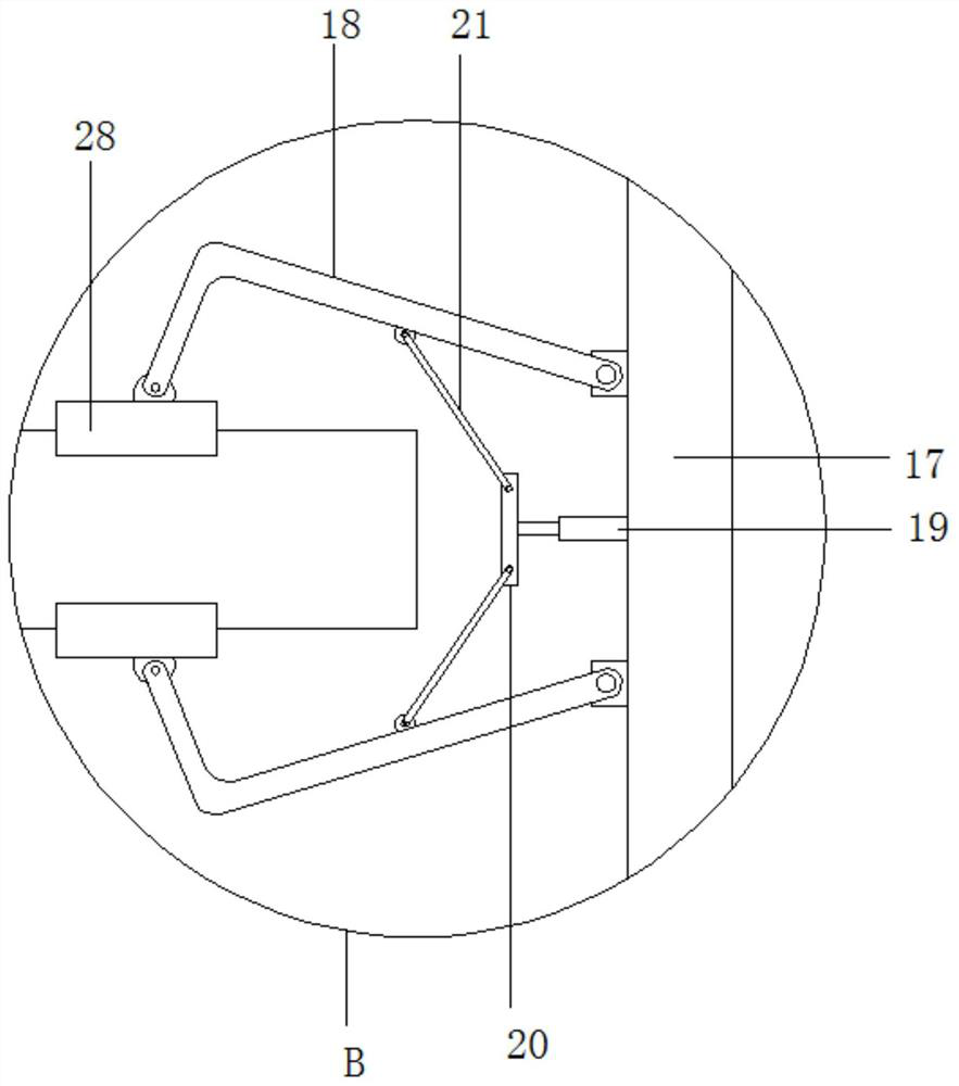
[0025] refer to Figure 1-6 , an automatic laser cutting device for slender pipes, comprising a base 1, a vertical plate 2, a mounting plate 3 and a support rod 4 are fixed on the top of the base 1, the mounting plate 3 is located between the vertical plate 2 and the support rod 4, the base 1 is provided with a top plate 5, the top of the vertical plate 2, the mounting plate 3 and the support rod 4 are fixedly connected with the top plate 5, the vertical plate 2 is provided with a discharge hole 6, and the side of the vertical plate 2 close to the mounting plate 3 is fixed with a Two horizontal plates 7 are arranged horizontally, and a horizontally arranged pipe body...


PUM


Abstract

The invention belongs to the technical field of laser cutting, and particularly relates to an automatic laser cutting device and method for long and thin pipes. The automatic laser cutting device comprises a base, wherein a vertical plate, a mounting plate and a supporting rod are fixed to the top of the base, the mounting plate is located between the vertical plate and the supporting rod, and a top plate is arranged above the base; and the top of the vertical plate, the top of the mounting plate and the top of the supporting rod are fixedly connected with the top plate, a discharging hole is formed in the vertical plate, two horizontally-arranged horizontal plates are fixed to the side, close to the mounting plate, of the vertical plate, a horizontally-arranged pipe body is rotationally mounted on the mounting plate, and a rotating mechanism used for rotating the pipe body is arranged on the mounting plate. According to the automatic laser cutting device and method for long and thin pipes, a laser cutting assembly conducts circular motion and conducts circular rotation around the axes of pipes to cut the pipes, all the pipes are cut trustingly, the distances between the laser cutting assembly and the cutting peripheries of the pipes are the same, the cutting efficiency is greatly improved, electric operation is achieved, and the use quality is high.

Description

technical field [0001] The invention relates to the technical field of laser cutting, in particular to an automatic laser cutting device and method for slender pipes. Background technique [0002] Laser cutting, a technique of cutting material using a laser, is often used in industrial manufacturing applications, but is also starting to be used by schools, small businesses and hobbyists. Laser cutting generally works by directing high-power laser output through optics. Laser optics and numerical control for guiding the material or guiding the resulting laser beam [0003] The existing automatic laser cutting device for slender pipes has low cutting efficiency. It is troublesome to cut pipes of different thicknesses, and the cutting efficiency is low. During the cutting process, as the distance between the laser cutting components and the cutting depth gradually increases, the cutting efficiency is not Similarly, at the same time, the cut pipe falls after cutting, which is ...

Claims


Application Information

Patent Timeline
Patent Type & Authority Applications(China)
IPC IPC(8): B23K26/02B23K26/38B23K26/70
CPCB23K26/38B23K26/02B23K26/702
Inventor 黄爱斌
Owner 江西晖旭实业有限公司
Learn More