Laser cutting machine tool workbench facilitating material taking

A laser cutting and workbench technology, applied in laser welding equipment, manufacturing tools, metal processing equipment, etc., can solve the problems of increasing production costs, wasting time, and difficulty in manually picking up distance workpieces, and achieving the effect of simple structure

Pending Publication Date: 2021-06-25
江苏领翰智能激光科技有限公司
View PDF0 Cites 0 Cited by
  • Summary
  • Abstract
  • Description
  • Claims
  • Application Information

AI Technical Summary

Problems solved by technology

[0003] The purpose of the present invention is to provide a laser cutting machine tool workbench that is convenient for picking up materials, so as to solve the problem in the prior art that when cutting plates with a large-format laser cutting machine, it is difficult to manually pick up workpieces that are far away, and the workpieces are made of plates. It is cut out and laid flat on the laser cutting machine table, which is inconvenient for centralized picking, wastes time, and increases production costs.

Method used


Image

  • Laser cutting machine tool workbench facilitating material taking
  • Laser cutting machine tool workbench facilitating material taking

Examples


Embodiment

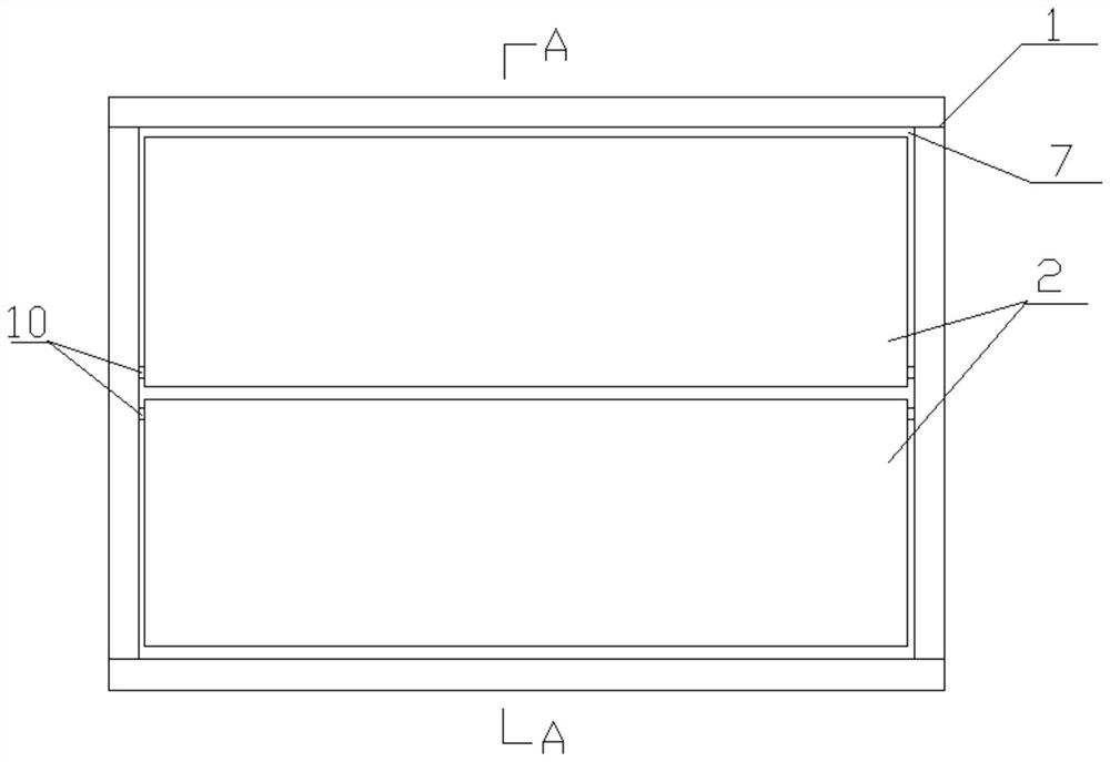
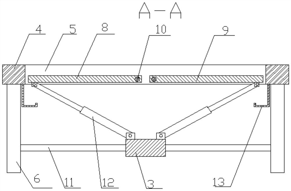
[0014] Example: such as figure 1 and figure 2 As shown, a laser cutting machine tool workbench that is convenient for retrieving materials includes a bed 1, a workbench 2 and a support plate 3, the bed 1 includes a beam 4, a longitudinal beam 5 and a bed leg 6, and the beam 4 and the longitudinal beam 5 are respectively There are two, the two ends of the two crossbeams 4 are fixedly connected with a longitudinal beam 5 respectively, and the lower sides of the two ends of each crossbeam 4 are respectively fixedly connected with a bed leg 6, and the two crossbeams 4 and the two longitudinal beams 5 form a The bed frame 7 and the workbench 2 are arranged in the bed frame 7. The workbench 2 includes a first workbench 8 and a second workbench 9. The sides of the first workbench 8 and the second workbench 9 away from the beam 4 respectively pass through a rotating shaft 10 Connected with the longitudinal beam 5, the lower sides of the two longitudinal bed legs 6 are respectively f...


PUM

PropertyMeasurementUnit
angleaaaaaaaaaa

Abstract

The invention discloses a laser cutting machine tool workbench facilitating material taking. The laser cutting machine tool workbench comprises a machine tool body, a workbench body and a supporting plate, the machine tool body comprises two cross beams, two longitudinal beams and two machine tool legs, each of the two ends of the two cross beams is fixedly connected with one longitudinal beam, and the lower sides of the two ends of each cross beam are each fixedly connected with one machine tool leg. The two cross beams and the two longitudinal beams define a machine tool frame, the workbench body is arranged in the machine tool frame and comprises a first workbench body and a second workbench body, the sides, away from the cross beams, of the first workbench body and the second workbench body are connected with the longitudinal beams through rotating shafts respectively, and the lower sides of the two longitudinal machine tool legs are fixedly connected with connecting rods respectively. The middles of the two connecting rods are fixedly connected with the two ends of the supporting plate respectively, each side of the supporting rod is connected with a hydraulic cylinder through a pin shaft, the top ends of the two hydraulic cylinders are connected with the side, close to the cross beams, of the workbench body through pin shafts respectively, L-shaped guide grooves are formed in the inner sides of the two cross beams respectively, and the laser cutting machine tool workbench is simple in structure and capable of picking up workpieces easily and rapidly.

Description

technical field [0001] The invention belongs to the technical field of laser cutting machines, and in particular relates to a laser cutting machine tool workbench which is convenient for taking materials. Background technique [0002] Laser cutting is to focus the laser emitted from the laser into a high-power-density laser beam through the optical path system. The laser beam is irradiated on the surface of the workpiece to make the workpiece reach the melting point or boiling point. At the same time, the high-pressure gas coaxial with the beam will melt or gas Blow away the chemical metal, along with the movement of the beam and the relative position of the workpiece, the material finally forms a slit, so as to achieve the purpose of cutting, and finally the processed plate and workpiece are manually removed from the workbench. In the prior art, when When cutting plates with a large-format laser cutting machine, it is difficult to manually pick up workpieces that are far aw...

Claims


Application Information

Patent Timeline
Patent Type & Authority Applications(China)
IPC IPC(8): B23K26/38B23K26/70
CPCB23K26/38B23K26/702
Inventor 杨旭东
Owner 江苏领翰智能激光科技有限公司
Why Eureka
Try Eureka