
Robot trajectory planning method and system for ingot repairing process

A technology of trajectory planning and robotics, applied in the direction of program control manipulators, manipulators, manufacturing tools, etc., can solve problems such as difficult non-ferrous metal ingot repair, difficult to plan trajectory, dimension disaster, etc., to achieve the effect of reducing computational complexity

Active Publication Date: 2021-06-25
NANKAI UNIV
View PDF7 Cites 3 Cited by
  • Summary
  • Abstract
  • Description
  • Claims
  • Application Information

AI Technical Summary

Problems solved by technology

Although the typical "three-segment" acceleration trajectory can meet the requirements of a large-scale uniform velocity segment, it will cause a "dimensional disaster" with the increase of the robot's degree of freedom; although the existing optimal trajectory planning method using path parameterization is effective The "curse of dimensionality" is avoided, but it is difficult to plan a trajectory with a large range of constant velocity segments, so it is difficult to apply it to non-ferrous metal ingot repairing operations

Method used


Image

  • Robot trajectory planning method and system for ingot repairing process
  • Robot trajectory planning method and system for ingot repairing process
  • Robot trajectory planning method and system for ingot repairing process

Examples


Embodiment 1

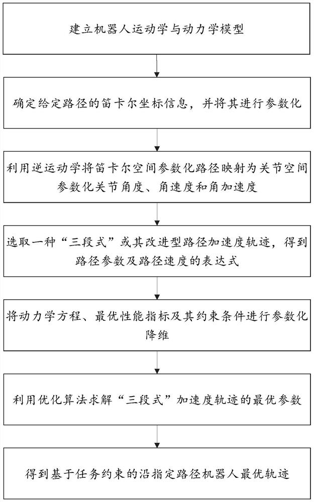
[0029] Such as figure 1 As shown, a robot trajectory planning method, including:

[0030] Obtain a given path, introduce path parameters, and parametrically represent the Cartesian coordinates of the given path;

[0031] Map the parameterized Cartesian coordinates of the path to the joint position, velocity and acceleration of the robot; select a three-segment path acceleration trajectory or its improved path acceleration trajectory to obtain the expression of the path parameters and their derivatives; use the parameterized Joint variables, velocities and accelerations parameterize the robot kinematics and dynamics equations and obtain performance index functions;

[0032] According to the performance index function, the optimization algorithm is used to solve the optimal parameters of the path acceleration trajectory, and the robot trajectory along the given path under the optimal parameters is obtained.

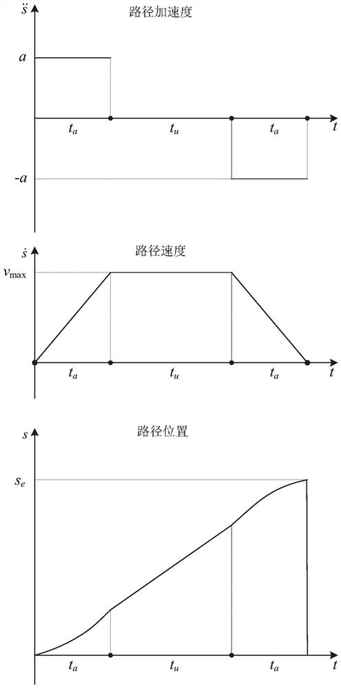
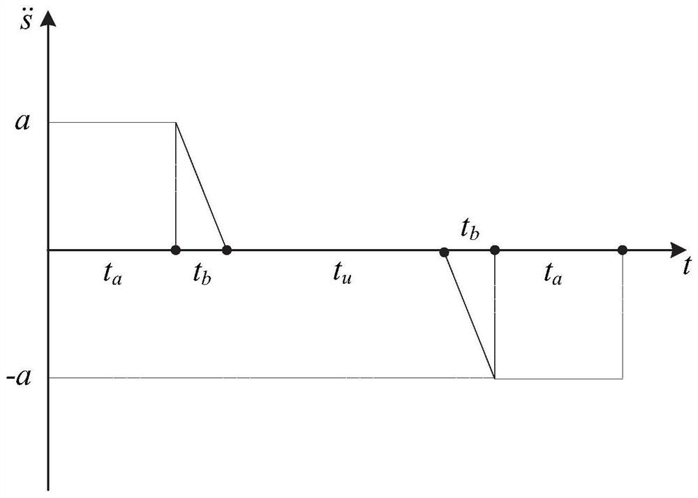
[0033] Specifically, the path acceleration trajectory is a three-seg...

Embodiment 2

[0081] A robot trajectory planning system, comprising:

[0082] The data collection module is configured to obtain a given path, introduce path parameters, and parametrically represent the Cartesian coordinates of the given path;

[0083] The data processing module is configured to map the parameterized Cartesian coordinates of the path to the joint position, velocity and acceleration of the robot; select a three-segment path acceleration trajectory or an improved path acceleration trajectory to obtain the path parameters and their derivatives Expression; use parameterized joint variables, speed and acceleration to parameterize robot kinematics and dynamics equations, and obtain performance index functions;

[0084] The optimal parameter determination module is configured to use an optimization algorithm to solve the optimal parameters of the path acceleration trajectory according to the performance index function, and obtain the robot trajectory along the given path under the...

Embodiment 3

[0087] A computer-readable storage medium is used for storing computer instructions. When the computer instructions are executed by a processor, the robot trajectory planning method described in the above-mentioned embodiments is completed.


PUM


Abstract

The invention provides a robot trajectory planning method and system. The method comprises: obtaining a given path, introducing path parameters, and performing parameterized representation on Cartesian coordinates of the given path; mapping the parameterized Cartesian coordinates of the path into the joint position, speed and acceleration of a robot; selecting a three-section path acceleration trajectory or an improved path acceleration trajectory thereof, and obtaining an expression of path parameters and derivatives thereof; parameterizing kinematics and kinetic equations of the robot by using the parameterized joint variable, speed and acceleration, and obtaining a performance index function; and according to the performance index function, solving an optimal parameter of the path acceleration trajectory by using an optimization algorithm, and obtaining a robot trajectory along the given path under the optimal parameter. The dimension of the optimal trajectory planning problem along the specified path is reduced, the calculation complexity is reduced, and the planned trajectory comprises a large-range constant-speed section, so that the method is more suitable for being applied to metal ingot burr trimming operation.

Description

technical field [0001] The present disclosure relates to the technical field of non-ferrous metal production, in particular to an industrial robot trajectory planning method for metal ingot repairing. Background technique [0002] The statements in this section merely provide background information related to the present disclosure and may not necessarily constitute prior art. [0003] The non-ferrous metallurgy industry is an important industry in the modern industry at home and abroad. In the non-ferrous metal production process, after the molten metal is condensed and formed into a metal ingot in the mold, there are irregular burrs around the metal ingot, which affects the product quality. Manual grinding of burrs is time-consuming and labor-intensive, and the efficiency is low. The working environment is high temperature and there is heat radiation, which affects human health. Moreover, the ingot repairing action is simple and repetitive, without rigid technical requir...

Claims


Application Information

Patent Timeline
IPC IPC(8): B25J9/16
CPCB25J9/16B25J9/1664B25J9/1679
Inventor 孙宁桑文闯邱泽昊张程琳方勇纯
Owner NANKAI UNIV
Learn More