Metal mask cutting protection equipment

A technology for metal masks and protective equipment, which is applied in glass manufacturing equipment, glass cutting devices, pollution prevention methods, etc., can solve problems such as scratches, splashes, and health hazards for workers, and achieve continuous The effect of increasing transportation and improving practicality

Active Publication Date: 2021-06-25
常州高光半导体材料有限公司
View PDF8 Cites 2 Cited by
  • Summary
  • Abstract
  • Description
  • Claims
  • Application Information

AI Technical Summary

Problems solved by technology

[0002]In the industry, it is also called photomask, mask plate, English name MASK or PHOTOMASK, material: quartz glass, metal chrome and photosensitive glue, this product is made of quartz glass The substrate is plated with a layer of metal chromium and photosensitive glue to become a photosensitive material. The designed circuit pattern is exposed on the photosensitive glue through an electronic laser device, and the exposed area will be developed. On the metal chromium The circuit pattern is formed, which becomes a photomask similar to the exposed film, and then applied to the projection positioning of the integrated circuit, and the projected circuit is photoetched by the integrated circuit photolithography machine, and there will be spattering and scrapping when it is cut. hidden danger, and the dust generated during the cutting process will cause harm to the health of the staff, and the material of the mask plate is a quartz glass substrate, which is easy to cause scratches when it is clamped before cutting, so the metal mask plate is proposed here Cutting protective equipment to solve the above problems

Method used


Image

  • Metal mask cutting protection equipment
  • Metal mask cutting protection equipment
  • Metal mask cutting protection equipment

Examples


Embodiment Construction

[0025] The following will clearly and completely describe the technical solutions in the embodiments of the present invention with reference to the accompanying drawings in the embodiments of the present invention. Obviously, the described embodiments are only some, not all, embodiments of the present invention.

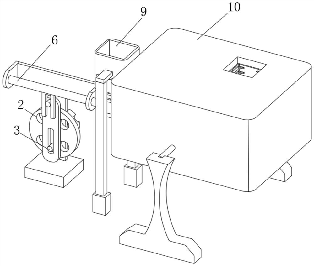
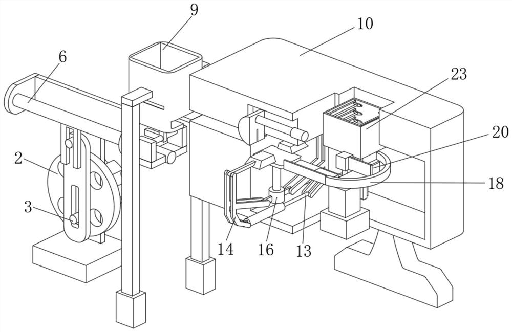
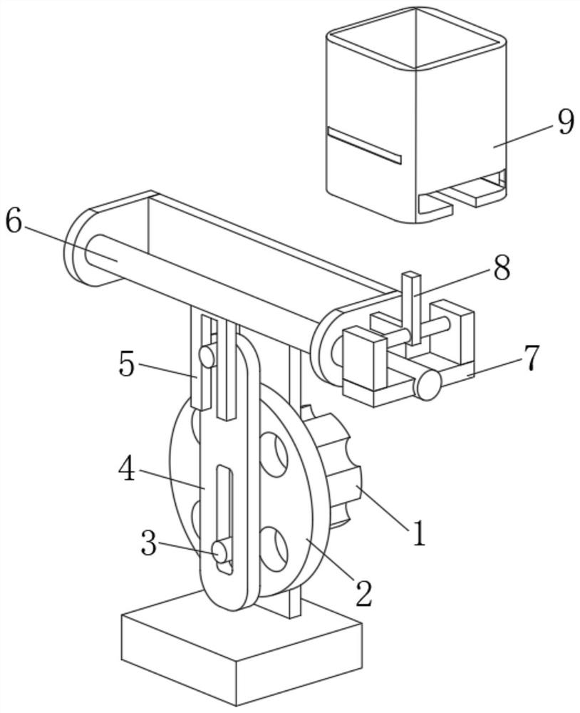
[0026] see Figure 1 to Figure 6 , the present invention provides a technical solution: metal mask cutting protection equipment, including a first servo motor 1, a drive disc 2 is fixedly sleeved on the output shaft of the first servo motor 1, and a drive disc is fixedly connected to the edge of the front of the drive disc 2. Column 3, the outer surface of the driving column 3 is movably socketed with one end of the driving sleeve rod 4, and the lower end of the driving sleeve rod 4 is provided with a driving groove, and the driving column 3 is movably socketed in the driving groove provided at the lower end of the driving sleeve rod 4 to drive The four sides of the ...


PUM


Abstract

The invention discloses metal mask cutting protection equipment, and relates to the technical field of mask cutting protection equipment, in particular to metal mask cutting protection equipment. The equipment comprises a first servo motor, an output shaft of the first servo motor is fixedly sleeved with a driving disc, the edge of the front face of the driving disc is fixedly connected with a driving column, and the outer surface of the driving column is movably sleeved with one end of a driving sleeve rod. According to the metal mask cutting protection equipment, the upper surface of a clamping jaw is a flat rectangle, a fixing notch is formed in the inward side of the upper surface of the clamping jaw, and the fixing notch is matched with a second hydraulic telescopic rod, a bearing table, a lifting sleeve and a ratchet wheel, so that a mask conveyed by a poke rod can be conveyed to the clamping jaw by the bearing table, the mask can be cut in the inner cavity of a protective case and taken on the outer side of the protective case, and the hidden danger caused by splashing of crushed materials when the mask is cut can be effectively solved.

Description

technical field [0001] The invention relates to the technical field of mask cutting protection equipment, in particular to metal mask cutting protection equipment. Background technique [0002] In the industry, it is also called photomask, mask plate, English name MASK or PHOTOMASK, material: quartz glass, metal chrome and photosensitive glue, this product is made of quartz glass as the substrate, and a layer of metal chrome and photosensitive glue is plated on it , become a photosensitive material, expose the designed circuit pattern on the photosensitive adhesive through the electronic laser equipment, the exposed area will be developed, and the circuit pattern will be formed on the metal chromium, which becomes a photomask similar to the exposed film. Then it is applied to the projection positioning of the integrated circuit, and the projected circuit is photo-etched through the integrated circuit lithography machine, and there will be hidden dangers when cutting the proj...

Claims


Application Information

Patent Timeline
IPC IPC(8): C03B33/03B08B17/02
CPCC03B33/03B08B17/02
Inventor 钱超杨柯牛恩众余强根
Owner 常州高光半导体材料有限公司
Why Eureka
Try Eureka