

Steel rail shock absorber
A shock absorber and rail technology, applied in the field of rail transit, can solve the problems of changing design stiffness value, poor low frequency control effect, and high maintenance and repair costs, reducing the transmission of vibration energy, achieving vibration reduction effect, and realizing broadband. Effect
- Summary
- Abstract
- Description
- Claims
- Application Information
AI Technical Summary
Problems solved by technology
Method used
Image

Examples
Embodiment 1
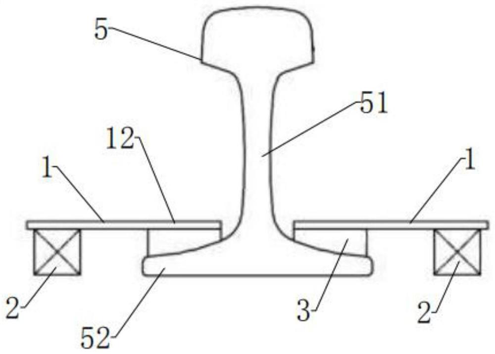
[0053] Such as Figure 1~2 and Figure 15 As shown, this embodiment provides a rail damper installed on both sides of the rail, including a leaf spring unit 1 and a tuning mass unit 2 that cantilever a certain moment arm length, and one end of the leaf spring unit 1 is connected to the tuning mass unit 2 , the constrained point 12 at the other end of the leaf spring unit 1 is connected to the constraint fulcrum 3 of the rail, and the leaf spring unit 1 is perpendicular to the length direction of the rail. The restraint fulcrum 3 is set on the upper surface of the rail foot on both sides of the rail waist, and the contact surface of the restraint fulcrum 3 is consistent with the upper surface of the rail foot. The restraint fulcrum 3 is fixed on the rail surface by gluing, welding or fixing fixtures. The connection between the plate spring unit 1 , the constraint fulcrum 3 and the tuning mass unit 2 can be connected by gluing, welding, fastener connection or integral molding. ...
Embodiment 2
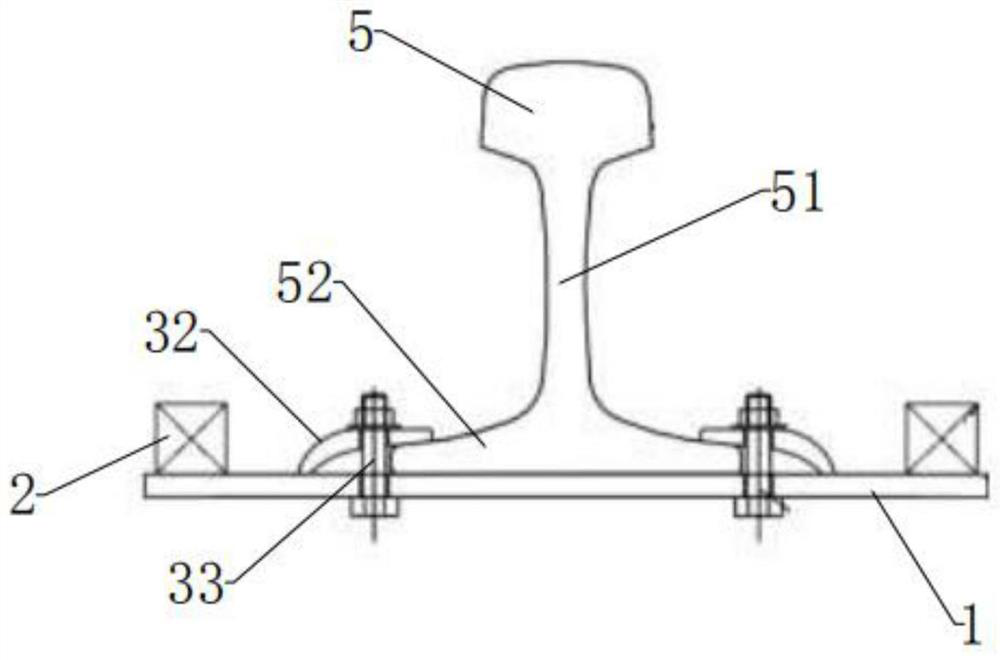
[0057] Such as image 3 As shown, in this embodiment, on the basis of Embodiment 1, the rail damper is arranged at the bottom of the rail. The leaf spring unit 1 is fixed on the bottom of the rail by two fixing fixtures, and the tuning mass unit 2 is installed at both ends of the leaf spring unit 1 .
[0058] The fixing fixture includes a clip 32 and a screw 33, wherein one end of the clip 32 is connected to the leaf spring unit 1, the other end of the clip 32 is buckled and pressed on the rail foot of the rail, and the double-ended screw 33 passes through the clip 32 and the plate The spring unit 1 fixedly connects the leaf spring unit 1 with the rail foot 52 of the rail.
Embodiment 3
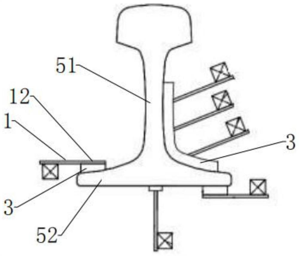
[0060] Such as Figure 4 As shown, this embodiment provides a rail damper installed on both sides of the rail, including a leaf spring unit 1 and a tuning mass unit 2 that cantilever a certain moment arm length, and the length direction of the leaf spring unit 1 is parallel to that of the rail. In the length direction, the constrained points 12 at both ends of the leaf spring unit 1 are connected to the restraint fulcrum 3 of the rail. The two restraint fulcrums 3 are set on the upper surface of the rail foot 52 on the same side of the rail. coincidentally, the constraint fulcrum 3 is fixed on the rail surface by gluing, welding or fixing fixtures. The tuning mass unit 2 is connected at the middle of the leaf spring unit 1 , and the tuning mass unit 2 is located between two constrained points 12 .
[0061] Other structures are the same as in Embodiment 1.
PUM
 Abstract
Description
Claims
Application Information