
Sludge pumping equipment for river sewage treatment

A sewage treatment and river channel technology, applied in the direction of earth mover/shovel, mechanically driven excavator/dredger, construction, etc., can solve the problems of small extraction range, damage to the mouth of the mud pumping pipe, and low efficiency. To achieve the effect of improving practicability, reducing damage and improving reliability

Inactive Publication Date: 2021-06-25
李军
View PDF6 Cites 0 Cited by
  • Summary
  • Abstract
  • Description
  • Claims
  • Application Information

AI Technical Summary

Problems solved by technology

Most of the sludge treatment equipment is fixed in a certain place, and then pumped. This kind of pumping range is small and requires staff to move, resulting in low efficiency; some are located on the river surface for mobile pumping, but due to The bottom is uneven, which makes the mud pumping pipe located at the bottom of the river easy to hit the hard objects at the bottom. Over time, the mouth of the mud pumping pipe is damaged and the reliability of the mud pumping equipment is reduced.

Method used


Image

  • Sludge pumping equipment for river sewage treatment
  • Sludge pumping equipment for river sewage treatment
  • Sludge pumping equipment for river sewage treatment

Examples


Embodiment 1

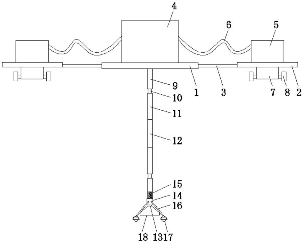
[0027] Such as figure 1 , Figure 3-5 As shown, a mud pumping equipment for river sewage treatment includes a first floating plate 1 and two second floating plates 2, the first floating plate 1 and the second floating plate 2 are connected by a connecting rod 3, and the second floating plate The bottom of the plate 2 is provided with a moving assembly, the first floating plate 1 is provided with a pump 4, and the second floating plate 2 is provided with a sludge tank 5. The pump 4 and the sludge tank 5 are connected through a connecting pipe 6. The first A mud pumping assembly is provided under the floating plate 1, and the pump 4 communicates with the mud pumping assembly;

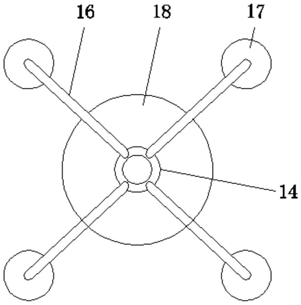
[0028] Described mud pumping assembly comprises conduction pipe 9 and mud pumping pipe 13, and mud pumping pipe 13 is communicated with pump 4 by conducting pipe 9, and the bottom end of mud pumping pipe 13 is provided with mud pumping port 18, and the top of mud pumping pipe 13 Extending into the insid...

Embodiment 2

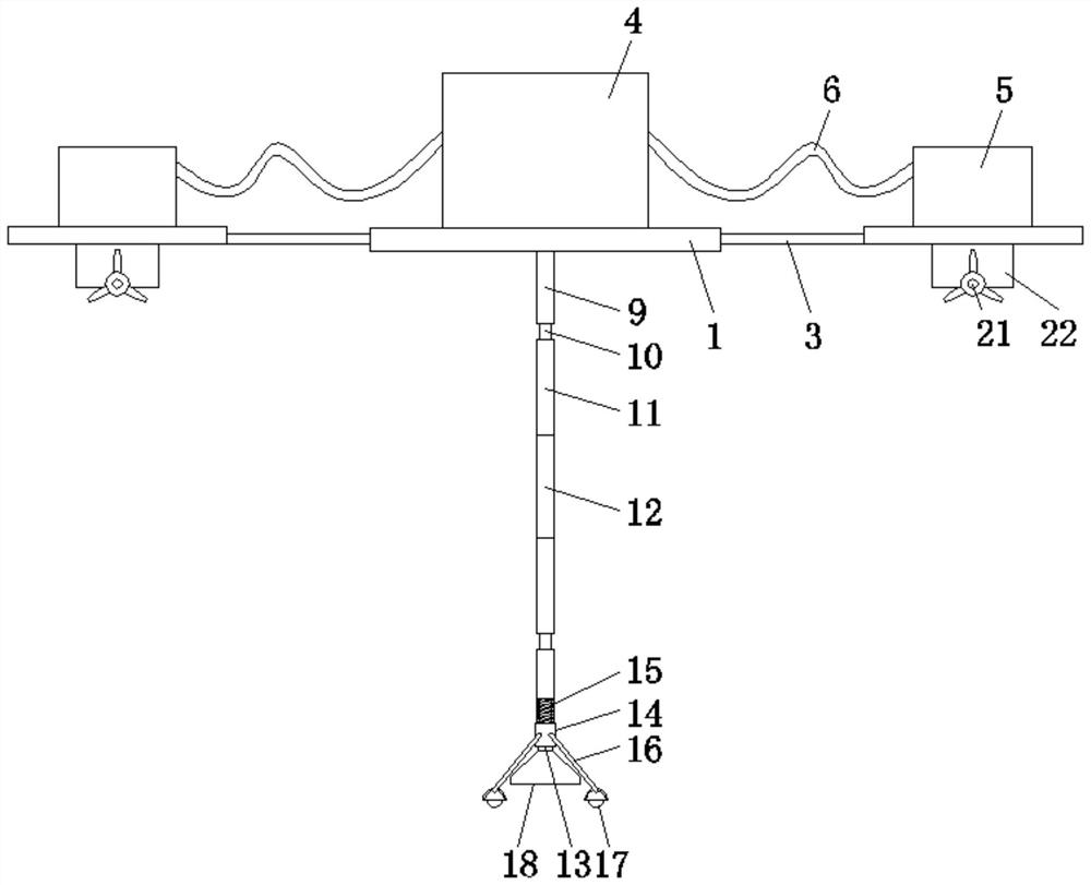
[0039] A mud pumping device for river sewage treatment, comprising a first floating plate 1 and two second floating plates 2, the first floating plate 1 and the second floating plate 2 are connected by a connecting rod 3, the second floating plate 2 There is a moving assembly at the bottom, a pump 4 is provided on the first floating plate 1, a sludge tank 5 is provided on the second floating plate 2, the pump 4 and the sludge tank 5 are connected through a connecting pipe 6, and the first floating plate 1 The bottom of the pump is provided with a mud pumping assembly, and the pump 4 communicates with the mud pumping assembly;

[0040] Described mud pumping assembly comprises conduction pipe 9 and mud pumping pipe 13, and mud pumping pipe 13 is communicated with pump 4 by conducting pipe 9, and the bottom end of mud pumping pipe 13 is provided with mud pumping port 18, and the top of mud pumping pipe 13 Extending into the inside of the conduction pipe 9, the mud pumping pipe 13...


PUM


Abstract

The invention discloses sludge pumping equipment for river sewage treatment. The equipment comprises a first floating plate and two second floating plates, wherein the first floating plate is connected with the second floating plates through connecting rods, the bottom of each second floating plate is provided with a moving assembly, the first floating plate is provided with a pump, the second floating plates are provided with a sludge box, the pump is communicated with the sludge box through a connecting pipe, a mud pumping assembly is arranged below the first floating plate, and the mud pumping assembly comprises a conduction pipe and a mud pumping pipe. Through a self-induction unit, stable mud pumping at an uneven river bottom can be achieved, obstacles or protruding places can be effectively crossed, and the reliability of the equipment is improved; a communicating pipe is in threaded connection with the conduction pipe through a threaded pipe, preliminary adjustment can be conducted according to the depth of a river surface, and the practicability of the equipment is improved; and the inner wall of a cutting pipe is spiral, and cutting blades on the inner wall of the cutting pipe realize cutting of hard substances in sludge, so that damage of the hard substances to pipelines in the equipment is reduced, and the reliability of the equipment is improved.

Description

technical field [0001] The invention relates to the field of sewage treatment equipment, in particular to a mud pumping equipment for river sewage treatment. Background technique [0002] Sewage treatment: the process of purifying sewage to meet the water quality requirements for discharge into a certain water body or for reuse. Sewage treatment is widely used in various fields such as construction, agriculture, transportation, energy, petrochemical, environmental protection, urban landscape, medical treatment, catering, etc., and it is also increasingly entering the daily life of ordinary people. [0003] Among the existing sewage treatment equipment, some of them are used for sludge treatment in river sewage treatment. Most of the sludge treatment equipment is fixed in a certain place, and then pumped. This kind of pumping range is small and requires staff to move, resulting in low efficiency; some are located on the river surface for mobile pumping, but due to The botto...

Claims


Application Information

Patent Timeline
Patent Type & Authority Applications(China)
IPC IPC(8): E02F3/92E02F3/90
CPCE02F3/9275E02F3/905E02F3/907
Inventor 李军
Owner 李军
Learn More