
Pipeline connecting structure for drainage basin pollution control and connecting method thereof

A technology of pollution control and connection method, which is applied in the direction of pipeline support, sleeve/socket connection, pipe/pipe joint/pipe fitting, etc., can solve the problems of no sampling mechanism, no tensioning mechanism, no supporting mechanism, etc. Achieve the effect of firm pipe connection, avoid trouble, and avoid leakage problems

Pending Publication Date: 2021-06-25
JILIN JIANZHU UNIVERSITY
View PDF0 Cites 0 Cited by
  • Summary
  • Abstract
  • Description
  • Claims
  • Application Information

AI Technical Summary

Problems solved by technology

[0008] The purpose of the present invention is to provide a pipeline connection structure for watershed pollution control and its connection method to solve the problem that the pipeline connection structure for watershed pollution control on the market currently on the market does not have a tensioning mechanism, resulting in insufficient tightness of the pipeline connection. Leakage problem, and there is no support mechanism, which leads to changes in the topography of the connection structure and the influence of external force factors. At the same time, there is no sampling mechanism, which is not conducive to the problem of personnel sampling

Method used


Image

  • Pipeline connecting structure for drainage basin pollution control and connecting method thereof
  • Pipeline connecting structure for drainage basin pollution control and connecting method thereof
  • Pipeline connecting structure for drainage basin pollution control and connecting method thereof

Examples


Embodiment Construction

[0029] The following will clearly and completely describe the technical solutions in the embodiments of the present invention with reference to the accompanying drawings in the embodiments of the present invention. Obviously, the described embodiments are only some, not all, embodiments of the present invention. Based on the embodiments of the present invention, all other embodiments obtained by persons of ordinary skill in the art without making creative efforts belong to the protection scope of the present invention.

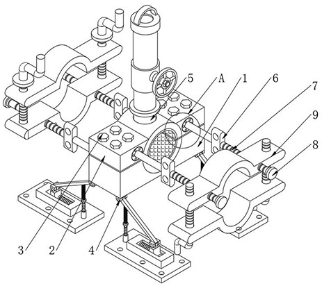
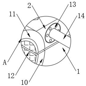
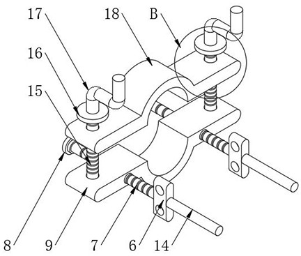
[0030] see Figure 1-7 , the present invention provides a technical solution: a pipeline connection structure and connection method for watershed pollution control, including a connection base plate 1, a connection block 2, a fixing bolt 3, a first connection hinge 4, a connection pipe 5, a rotating block 6, Tension screw 7, limit nut 8, first clamping arc plate 9, first connecting arc plate 10, second connecting arc plate 11, rubber plate 2, connecting bearin...


PUM


Abstract

The invention discloses a pipeline connecting structure for drainage basin pollution control and a connecting method thereof. The pipeline connecting structure comprises a connecting bottom plate, an open groove is formed in the middle of the top end of the connecting bottom plate, the inner wall of the open groove is fixedly connected with the bottom end of a first connecting arc plate, and the two sides of the top end of the connecting bottom plate are fixedly connected with the bottom ends of two connecting blocks through a plurality of fixing bolts correspondingly. And ends of the two connecting blocks are fixedly connected with the two ends of a second connecting arc plate correspondingly, mounting grooves are formed in the two ends of one side of the connecting bottom plate and the middles at one side of each of the two connecting blocks correspondingly, and a connecting bearing is fixedly mounted on the inner wall of each mounting groove. According to the pipeline connecting structure for drainage basin pollution control and the connecting method thereof, a tensioning mechanism is arranged, it can be guaranteed that pipeline connection is tighter, and the leakage problem is avoided; and a supporting mechanism is arranged, the pipeline connecting structure can be prevented from being influenced by terrain changes and external force factors, and meanwhile a sampling mechanism is arranged so that personnel sampling can be made more convenient. And drainage basin pollution treatment is facilitated.

Description

technical field [0001] The invention relates to the technical field of watershed pollution control, in particular to a pipeline connection structure and connection method for watershed pollution control. Background technique [0002] Watershed pollution refers to river pollution caused by human activities that discharge pollutants into rivers, which will not only cause damage to the river environment, but also endanger human health. After the watershed is polluted, personnel need to control the watershed, and the pipeline connection structure is needed to connect the pipelines in the watershed pollution treatment. [0003] Pipeline connection structures currently on the market for river basin pollution control: [0004] (1) When connecting the pipelines, if the connection is not strong enough, the connection position of the pipelines will leak. The existing pipeline connection structure does not have a tensioning mechanism, which will lead to insufficient tight connection o...

Claims


Application Information

Patent Timeline
IPC IPC(8): F16L41/02F16L41/10F16L41/12F16L41/16F16L55/115F16L21/06F16L3/10F16L3/20G01N1/10
CPCF16L41/021F16L41/10F16L41/12F16L41/16F16L55/115F16L21/065F16L3/1091F16L3/20G01N1/10
Inventor 曲智刘志生刘智张居奎
Owner JILIN JIANZHU UNIVERSITY
Learn More