
Foreign substance inspection method and foreign substance inspection apparatus

A foreign matter inspection and foreign matter technology, applied in the direction of measuring devices, optical devices, instruments, etc., can solve the problems of unconfirmed size, deterioration of lining yield, lack of safety management, etc., and achieve the effect of suppressing measurement errors

Pending Publication Date: 2021-06-25
TOYOTA JIDOSHA KK
View PDF1 Cites 0 Cited by
  • Summary
  • Abstract
  • Description
  • Claims
  • Application Information

AI Technical Summary

Problems solved by technology

[0007] However, as described in the above-mentioned Japanese Patent No. 6508435, the method of using X-rays to detect buried foreign objects is lacking in terms of cost increases due to the introduction of X-ray irradiation equipment, etc., and safety management of X-rays (radiation). reality
[0008] Therefore, in the current situation, when the presence of buried foreign matter in the product can be vaguely recognized visually, the size is not confirmed, and all are handled as defective products, which causes deterioration of the yield rate of the inner liner and increases in cost.

Method used


Image

  • Foreign substance inspection method and foreign substance inspection apparatus
  • Foreign substance inspection method and foreign substance inspection apparatus
  • Foreign substance inspection method and foreign substance inspection apparatus

Examples


Embodiment approach 1

[0041] -Lining-

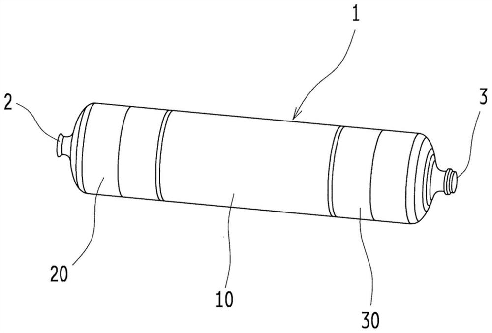
[0042] figure 1 It is a perspective view schematically showing the liner 1 of this embodiment. The inner liner 1 is, for example, a member constituting the inner casing of a hydrogen tank (not shown) mounted on a fuel cell vehicle, and is formed in a cylindrical shape with both ends closed, and can use the high-pressure gas used for power generation of the fuel cell in a sealed state. of hydrogen contained inside it.

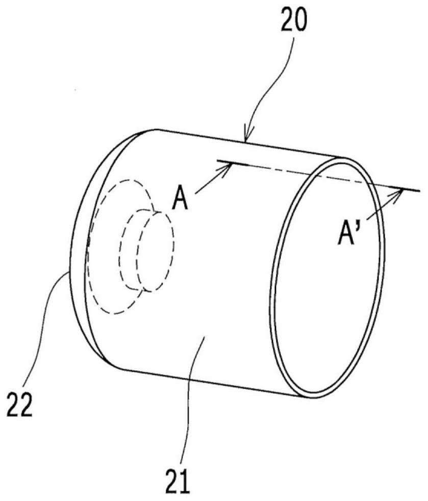
[0043] From the viewpoint of weight reduction, the lining 1 is made of resin, such as figure 1 As shown, a resin pipe 10 and two resin domes 20 and 30 are provided. These are joined (welded) in the axial direction so that one cylindrical tube 10 is sandwiched between two bottomed cylindrical domes 20, 30, and the aluminum joint 2, 3 is assembled to the two domes 20 and 30 located at both ends, whereby the liner 1 is formed into a closed cylindrical shape. Carbon fiber (not shown) is wound around the outer periphery of the inner liner 1 thu...

Embodiment approach 2

[0089] The difference between the present embodiment and the above-mentioned first embodiment is that the first projected image 41 projected by the inner light source 71 on the outer peripheral surface 21b of the dome 20 is also captured by the camera. Hereinafter, description will focus on points different from Embodiment 1. FIG.

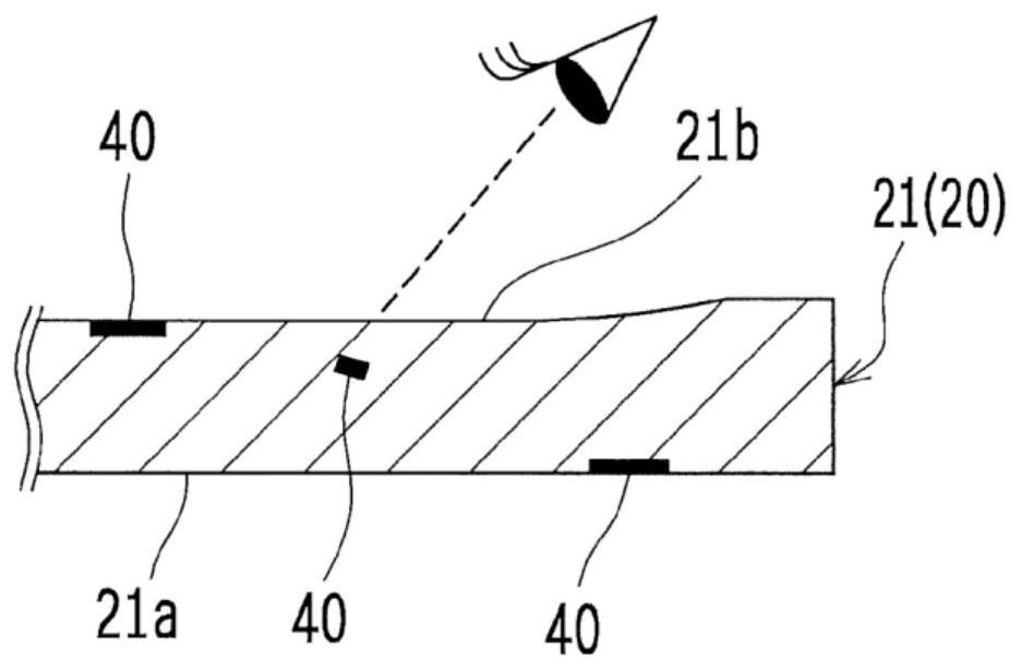
[0090]The inspector can visually measure the size of the first projected image 41 formed by projecting the light from the inner light source 71 on the outer peripheral surface 21 b of the dome 20 regardless of the size of the diameter of the inner liner 1 . On the other hand, for the second projected image 42 formed by projecting the light from the external light source 73 onto the inner peripheral surface 21 a of the dome 20 , it may be difficult for the examiner to visually measure it due to the size of the diameter of the lining 1 . size. Therefore, in the above-mentioned first embodiment, the second projected image 42 projected on the inner pe...


PUM


Abstract

Provided are a foreign substance inspection method for inspecting presence or absence of a foreign substance embedded in a tubular resin molded product, and a foreign substance inspection apparatus. The foreign substance inspection method includes: preparing a dome; a first measurement step of measuring a dimension of a first projection image of the embedded foreign substance; a second measurement step of measuring a dimension of a second projection image of the embedded foreign substance: and a calculation step of calculating the dimension of the embedded foreign substance based on a proportional relationship between the dimension of each of the projection images to a distance from a corresponding one of the light sources to the each of the projection images and the dimension of the embedded foreign substance to a distance from the corresponding one of the light sources to the embedded foreign substance.

Description

technical field [0001] The present invention relates to a foreign matter inspection method and a foreign matter inspection device for inspecting the presence or absence of foreign matter buried in a cylindrical resin molded product and having a size exceeding a predetermined threshold. Background technique [0002] Conventionally, there is known a fuel cell vehicle that is equipped with a fuel cell that generates electricity by chemically reacting hydrogen taken in from a hydrogen tank onboard and oxygen taken in from the atmosphere, and runs using the power generated by the fuel cell as a driving source. . From the viewpoint of weight reduction, a high-pressure tank is generally used as a hydrogen tank mounted on such a fuel cell vehicle, and the high-pressure tank has a closed cylindrical liner including a resin tube and a dome as an inner shell, And a high-strength shell is formed by winding carbon fiber around the outer peripheral surface of the inner liner. [0003] I...

Claims


Application Information

Patent Timeline
Patent Type & Authority Applications(China)
IPC IPC(8): G01N21/88G01B11/00
CPCG01N21/88G01B11/00G01N33/442G01N21/952G01N21/94Y02E60/50Y02E60/32G01N23/18G01N23/083G01N23/04Y02T90/40G06T2207/30108G01N2223/646G06T7/0004B29C45/768B29C2945/76147
Inventor 木村树浅田竜幸小池良树
Owner TOYOTA JIDOSHA KK
Learn More