Automatic optical detection method, system and equipment for circuit board components

An automatic optical inspection and circuit board technology, which is applied in the direction of material analysis, instruments, and measuring devices through optical means, can solve the unfavorable streamlined production of circuit boards, increase the workload and difficulty of making inspection templates, waste time and labor costs and other issues to achieve the effect of reducing the probability of human error, shortening the detection time, and reducing labor costs

Pending Publication Date: 2021-06-25
微讯智造(广州)电子有限公司
View PDF7 Cites 1 Cited by
  • Summary
  • Abstract
  • Description
  • Claims
  • Application Information

AI Technical Summary

Problems solved by technology
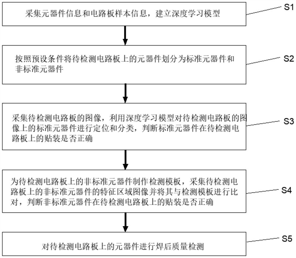
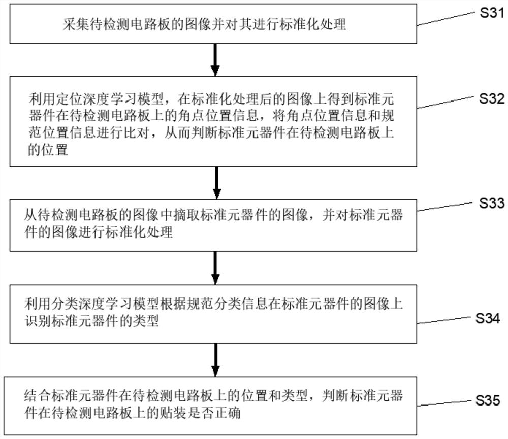
[0002] In the prior art, image grayscale combined with template matching is usually used to check the placement effect of components on the circuit board. It is necessary to set up individual inspection templates for all components on the circuit board. Different components have different Inspection items, different inspection items require different inspection templates, and then use template matching, color histogram, contour analysis and other traditional visual computing methods to distinguish the position, category and post-soldering quality of components on the circuit board, and then judge whether they meet Mounting standards, and different visual calculation methods have different resolution standards for different components, which will increase the workload and difficulty of making inspection templates, greatly wasting time and labor costs, and is also not conducive to the inspection of circuit boards. streamlined production

Method used


Image

  • Automatic optical detection method, system and equipment for circuit board components
  • Automatic optical detection method, system and equipment for circuit board components
  • Automatic optical detection method, system and equipment for circuit board components

Examples


Embodiment Construction

[0053] Orientation terms such as up, down, left, right, front, back, front, back, top, and bottom that are mentioned or may be mentioned in this specification are defined relative to their structures, and they are relative concepts. Therefore, it is possible to make corresponding changes according to its different positions and different usage states. Accordingly, these or other directional terms should not be construed as limiting terms.

[0054] The implementations described in the following exemplary examples do not represent all implementations consistent with the present disclosure. Rather, they are merely examples of approaches consistent with aspects of the disclosure as recited in the appended claims.

[0055] The terminology used in the present disclosure is for the purpose of describing particular embodiments only, and is not intended to limit the present disclosure. As used in this disclosure and the appended claims, the singular forms "a", "the", and "the" are in...


PUM


Abstract

The invention discloses an automatic optical detection method, system and equipment for circuit board components and a medium. The automatic optical detection method for the circuit board components comprises the following steps: collecting component information and circuit board sample information, and establishing a deep learning model; dividing the components on the circuit board to be detected into standard components and non-standard components according to a preset condition; acquiring an image of the circuit board to be detected, positioning and classifying the standard component by using the deep learning model, and judging whether the standard component is correctly mounted on the circuit board to be detected or not; and acquiring a feature region image of the non-standard component on the circuit board to be detected, comparing the feature region image with a detection template, and judging whether the mounting of the non-standard component on the circuit board to be detected is correct or not. According to the automatic optical detection method for the circuit board components, the detection of the standard component is automatic, the detection time is shortened, the detection precision is improved, the detection accuracy is ensured, and the labor cost is reduced.

Description

technical field [0001] The invention relates to the technical field of circuit board detection, in particular to an automatic optical detection method, system, equipment and computer-readable storage medium for circuit board components. Background technique [0002] In the prior art, image grayscale combined with template matching is usually used to check the placement effect of components on the circuit board. It is necessary to set up individual inspection templates for all components on the circuit board. Different components have different Inspection items, different inspection items require different inspection templates, and then use template matching, color histogram, contour analysis and other traditional visual computing methods to distinguish the position, category and post-soldering quality of components on the circuit board, and then judge whether they meet Mounting standards, and different visual calculation methods have different resolution standards for differ...

Claims


Application Information

Patent Timeline
Patent Type & Authority Applications(China)
IPC IPC(8): G01N21/956G01N21/01
CPCG01N21/01G01N21/956G01N2021/0112G01N2021/95638
Inventor 谭攻坚司徒希贤罗海妮李文高
Owner 微讯智造(广州)电子有限公司
Why Eureka
Try Eureka