
Novel artificial fish reef

An artificial fish reef, a new type of technology, applied in fish farming, application, climate change adaptation, etc., can solve the problems of external concrete cracking, difficulty in gathering fish, and easy corrosion of steel structures

Pending Publication Date: 2021-06-29
CHANGDAO COUNTY CHANGSHAN SEAFOOD CO LTD
View PDF0 Cites 1 Cited by
  • Summary
  • Abstract
  • Description
  • Claims
  • Application Information

AI Technical Summary

Problems solved by technology

[0003] Commonly used artificial fish reefs often use cement blocks or reinforced concrete with a square frame structure. In long-term use, the steel structure is easy to corrode, causing external concrete cracks, and the weight of cement and concrete is heavy, and the fish reef is easy to sink.
[0004] In view of the related technologies mentioned above, the inventor found that after the commonly used concrete or cement frame structure is put into the seabed, in the seabed with a lot of soft mud, the artificial reef is easy to sink into the mud under its own gravity during long-term use, and it is difficult to Achieve the effect of gathering fish, adding value to seaweed, and improving the living and growth environment of marine fish, shrimp, shellfish and algae

Method used


Image

  • Novel artificial fish reef
  • Novel artificial fish reef
  • Novel artificial fish reef

Examples


Embodiment 1

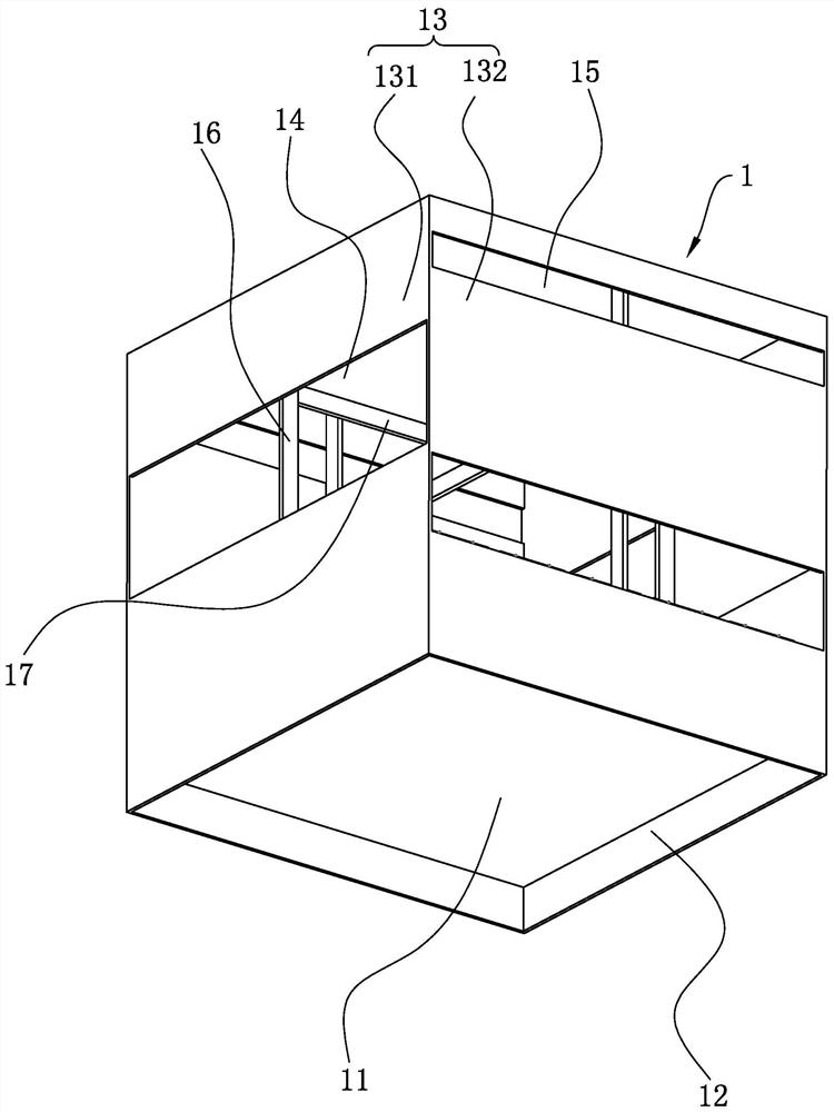
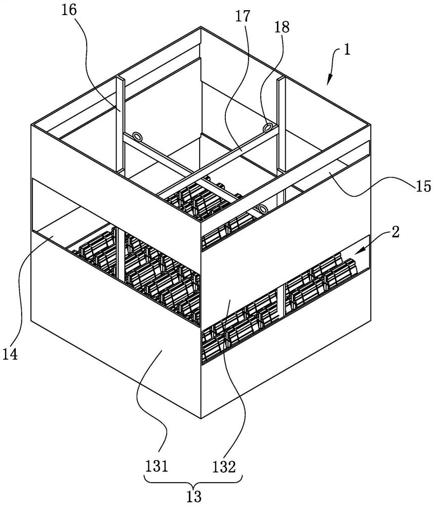
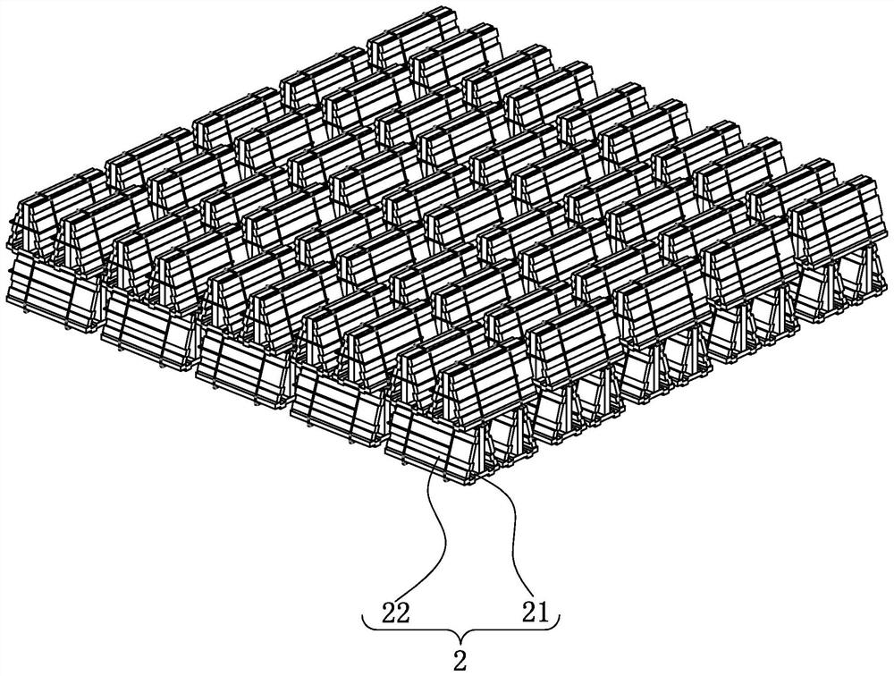
[0038] refer to figure 1 and figure 2 The novel artificial fish reef includes a reef body 1, and the reef body 1 includes a bottom plate 11 arranged in a square shape, the bottom plate 11 is surrounded by a baffle plate 13, the bottom plate 11 is located at one end of the baffle plate 13, and the side of the bottom plate 11 away from the baffle plate 13 is surrounded by a Bottom edge 12 is arranged. The height of the bottom edge 12 is 25cm. The baffle 13 is arranged perpendicular to the bottom plate 11 . During use, the bottom plate 11 of the reef body 1 is placed into the sea downwards, and the bottom edge 12 can go deep into the seabed, which is convenient for the reef body 1 to sink, and prevents the reef body 1 from tipping over. The bottom edge 12 and the bottom plate 11 will form a closed space with the seabed. Improve the stability of the reef 1, reduce the overall tilting or overturning of the reef 1 caused by direct contact between the bottom plate 11 and the bott...

Embodiment 2

[0049] refer to Figure 4 , The difference between this embodiment and Embodiment 1 is that the first water flow hole 14 and the second water flow hole 15 are both circular (or other polygonal or closed shapes, not shown in the figure). The first water flow hole 14 and the second water flow hole 15 arranged in a circle can also allow the sea current to flow through, and at the same time, their strength is greater than that of the elongated holes that pass through, so there is no need to reinforce the tie bars 16 .

Embodiment 3

[0051] refer to Figure 5 The difference between this embodiment and Embodiment 1 is that the four hoisting earrings 18 are respectively located at the upper ends of the four reinforcement bars 16 (or at the upper ends of the baffle 13, and are evenly distributed along the circumferential edge of the baffle 13, not shown in the figure ).


PUM


Abstract

The invention relates to a novel artificial fish reef, and belongs to the field of marine ranch equipment. The novel artificial fish reef comprises a reef body, the reef body comprises a bottom plate, baffles are arranged around the bottom plate, the bottom plate is located at the lower ends of the baffles, and bottom edges are arranged around the lower part of the bottom plate of the baffles. The closed flat bottom of the bottom plate exists, so that the stress area of the reef body is increased, and sinking of the reef body can be effectively slowed down and restrained; and meanwhile, a stable closed space can be formed between the reef body and the seabed through the reef bottom edge, the reef body is more balanced and stable, the situation that the reef body topples over due to the uneven seabed is reduced, and buoyancy can be provided below the bottom plate, so that the reef body is prevented from sinking.

Description

technical field [0001] This application relates to the field of marine ranch equipment, in particular to a new type of artificial fish reef. Background technique [0002] Artificial fish reef is a kind of artificial underwater fish-gathering and value-added algae equipment, which is used to improve the marine environment, attract marine life and fish to gather, and is often used in marine ranching to develop deep-sea recreational fishing industry. [0003] Commonly used artificial fish reefs often use cement blocks or reinforced concrete with a square frame structure. In long-term use, the steel structure is prone to corrosion, causing external concrete cracks, and the weight of cement and concrete is relatively heavy, and the fish reef is easy to sink. [0004] In view of the related technologies mentioned above, the inventor found that after the commonly used concrete or cement frame structure is put into the seabed, in the seabed with a lot of soft mud, the artificial ree...

Claims


Application Information

Patent Timeline
IPC IPC(8): A01K61/73
CPCA01K61/73Y02A40/81
Inventor 张巧英胡德燕侯杰路小光王德连王恒义秦建恺
Owner CHANGDAO COUNTY CHANGSHAN SEAFOOD CO LTD
Learn More