Battery replacement type pure electric heavy truck battery replacement system structure
A pure electric and electric system technology, applied in the field of heavy truck power exchange system, can solve the problems affecting the effective connection between the battery and the heavy truck, poor connection stability, etc., to improve the connection stability, prolong the service life, reduce the difficulty of installation and fixation and disassembly effect of difficulty
- Summary
- Abstract
- Description
- Claims
- Application Information
AI Technical Summary
Problems solved by technology
Method used
Image
Examples
Embodiment 1
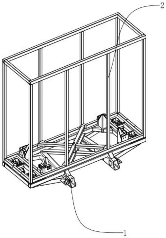
[0048] Such as figure 1 As shown, a locking mechanism of a pure electric heavy truck battery replacement system includes a vehicle-mounted battery replacement base 1 and a battery replacement battery box assembly 2 . The vehicle-mounted battery exchange base 1 is used to connect and fix the body of the pure electric heavy truck, and the battery-exchange battery box assembly 2 is used to install and fix the battery, so that the battery-exchange battery box assembly can be installed on the vehicle-mounted battery exchange base 1 2 After disassembly, charge and replace the battery box assembly 2 with the charged battery through the battery swap station.
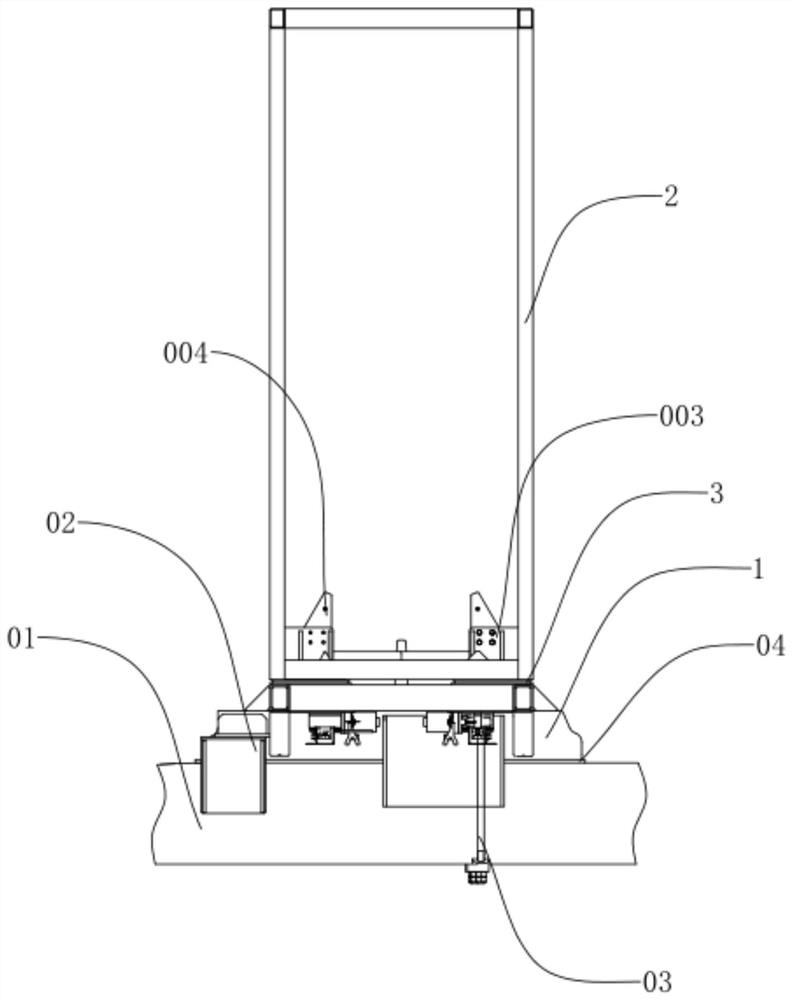
[0049] Such as figure 2 As shown, it also includes a frame assembly 01 connected with the heavy truck body. The upper end of the vehicle frame assembly 01 is provided with a fixed connecting plate 02 . The fixed connecting plate 02, the vehicle-mounted battery exchange base 1 and the frame assembly 01 are plugged and fixed w...
Embodiment 2
[0064] The difference between the second embodiment and the first embodiment is that the driving part in the second embodiment is the cylinder assembly 6 . Such as Figure 8 , Figure 9 As shown, the cylinder assembly 6 is provided with a piston rod 61 , and the piston rod 61 is fixedly connected with the universal joint 7 . The universal joint 7 is rotatably connected with a connecting rod body 8 , and the connecting rod body 8 is rotatably connected with a camshaft 9 . A spline is formed in the camshaft 9, and the bottom of the knob-type locking pin 4 is inserted into the camshaft 9 and engaged with the spline, so that when the cylinder assembly 6 drives the piston rod 61 to run, the connecting rod body 8 The connection of the universal joint 7 and the camshaft 9 drives the camshaft 9 to rotate. Wherein, the universal joint 7 is provided with a transfer U-shaped groove 71 . And a cam adapter portion 91 is provided on the outer peripheral side wall of the camshaft 9 . Bo...
Embodiment 3
[0068] The difference between the third embodiment and the second embodiment is that the driving parts in the third embodiment are the cylinder fixing base 002, the cylinder joint 0021 fixedly connected with the cylinder fixing base 002, and the driving cylinder 0022 whose one end is rotationally connected with the cylinder joint 0021. Such as Figure 10 As shown, wherein, the other end of the driving cylinder 0022 is connected with a cylinder pin 0023, and the cylinder pin 0023 is used for rotationally connecting with the camshaft 9, so as to effectively drive the camshaft 9 to perform circumferential reciprocating motion. Correspondingly, the camshaft 9 is engaged with the knob-type locking pin 4 through a spline.
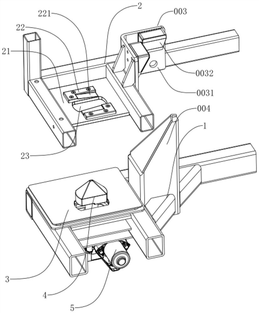
[0069] To sum up, through the mutual cooperation of the first-level guide assembly, the second-level guide assembly, and the third-level guide assembly, the wedge-shaped abutting pad 003 and the wedge-shaped insertion post 004 that cooperate with each other in th...
PUM
 Abstract
Description
Claims
Application Information
 - R&D
- Intellectual Property
- Life Sciences
- Materials
- Tech Scout
- Unparalleled Data Quality
- Higher Quality Content
- 60% Fewer Hallucinations
Browse by: Latest US Patents, China's latest patents, Technical Efficacy Thesaurus, Application Domain, Technology Topic, Popular Technical Reports.
© 2025 PatSnap. All rights reserved.Legal|Privacy policy|Modern Slavery Act Transparency Statement|Sitemap|About US| Contact US: help@patsnap.com


