Gravity compensator and bearing device
A technology of gravity compensation and acting force, applied in the field of magnetic attraction, can solve the problems of limited vibration isolation frequency, high noise, uncompact structure, etc., and achieve the effect of large magnetic action area
- Summary
- Abstract
- Description
- Claims
- Application Information
AI Technical Summary
Problems solved by technology
Method used
Image
Examples
Embodiment 1
[0046]For some high-precision industrial equipment, active vibration isolation is required to avoid external vibration and disturbance. Existing vibration isolation equipment uses airflow adjustment, which has the problems of high noise and limited vibration isolation efficiency.
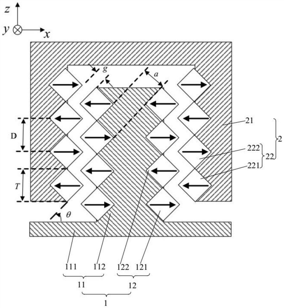
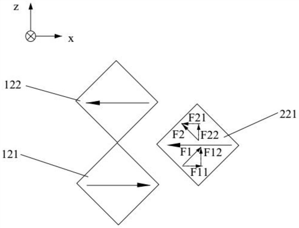
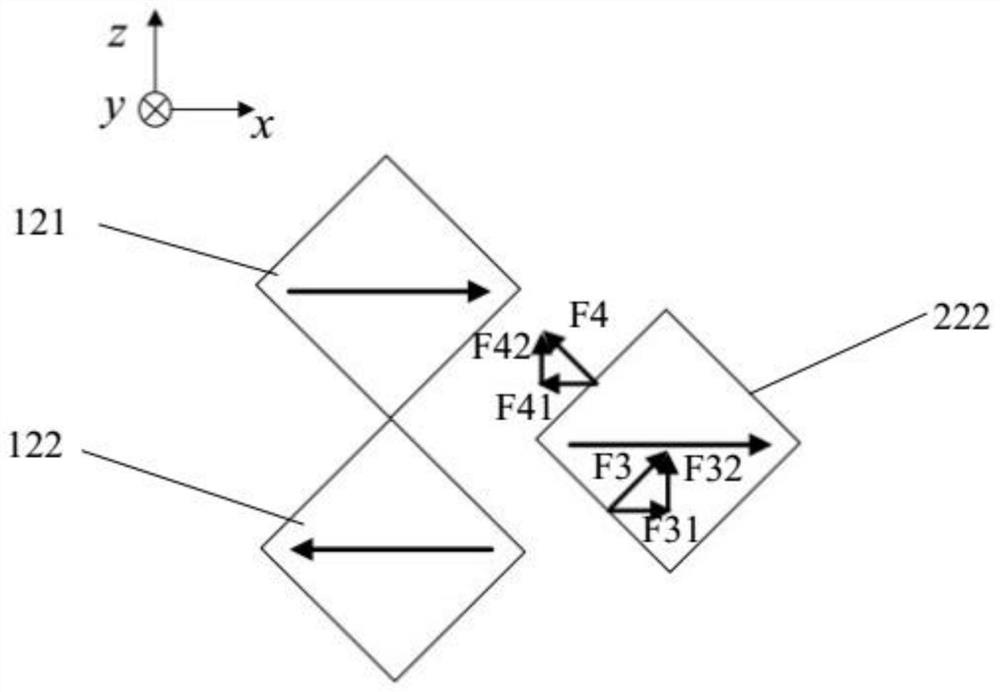
[0047] In order to solve this problem, this embodiment provides a gravity compensator, such as figure 1 As shown, the gravity compensator includes a first magnetic assembly 1 and a second magnetic assembly 2, the first magnetic assembly 1 and the second magnetic assembly 2 are not in contact with each other, and among the first magnetic assembly 1 and the second magnetic assembly 2 One is fixed, and the other is movable. The movable assembly is used to carry the load, and a magnetic force can be generated between the first magnetic assembly 1 and the second magnetic assembly 2, and the magnetic force realizes the support of the load. In order to achieve the purpose of gravity compensation.
[0048]...
Embodiment 2
[0072] The structural shape of this embodiment is the same as that of Embodiment 1, and the magnetization direction of the magnet is also the same. The only difference is that the fixed structure and the movable structure are interchangeable. Assembly 2, this embodiment is completely opposite to Embodiment 1. The fixed structure of this embodiment is the second magnetic assembly 2, and the movable structure is the first magnetic assembly 1, that is, the second magnetic assembly 2 is a stator, and the first magnetic assembly 1 is The mover, the second magnetic assembly 2 generates a magnetic force for the first magnetic assembly 1 to drive the first magnetic assembly 1 to move along the Z-axis direction, that is, the second main magnet 221 and the second auxiliary magnet 222 are used to move the first main magnet 221 together. The magnet 121 and the first secondary magnet 122 move upward along the Z axis. Since the top surface of the column 112 in the first magnetic assembly 1 ...
Embodiment 3
[0075] The structure of this embodiment is similar to that of Embodiment 1, and the only difference is that the shapes of the cross sections of the first main magnet 121, the first auxiliary magnet 122, the second main magnet 221 and the second auxiliary magnet 222 are the same as those of each magnet in Embodiment 1. rhombus in shape, such as Figure 6 As shown, the cross-sections of the first main magnet 121, the first auxiliary magnet 122, the second main magnet 221 and the second auxiliary magnet 222 in this embodiment are pentagonal, and the pentagon is not a regular equilateral pentagon. The first magnet array 12 and the second magnet array 22 form a zigzag structure on the side close to each other, and the first magnet array 12 and the second magnet array 22 are flush or not flush on the side away from each other. . As long as a regular zigzag gap is formed between opposite sides of the two arrays, there is no other limitation on the cross section. The magnetization d...
PUM
 Abstract
Description
Claims
Application Information
 - R&D
- Intellectual Property
- Life Sciences
- Materials
- Tech Scout
- Unparalleled Data Quality
- Higher Quality Content
- 60% Fewer Hallucinations
Browse by: Latest US Patents, China's latest patents, Technical Efficacy Thesaurus, Application Domain, Technology Topic, Popular Technical Reports.
© 2025 PatSnap. All rights reserved.Legal|Privacy policy|Modern Slavery Act Transparency Statement|Sitemap|About US| Contact US: help@patsnap.com


