Positioning device of intelligent valve positioner

A technology of intelligent valve and positioning device, applied in the direction of valve device, valve operation/release device, valve details, etc., can solve the problems of inconvenience of use, inability to adjust according to the needs of use, etc., to achieve convenient use, high adjustment and positioning efficiency, The effect of wide applicability

Inactive Publication Date: 2021-06-29
WENZHOU POLYTECHNIC
View PDF0 Cites 2 Cited by
  • Summary
  • Abstract
  • Description
  • Claims
  • Application Information

AI Technical Summary

Problems solved by technology

[0002] With the advancement of industrial technology, the automation control process has become the main development trend. Intelligent valves occupy an extremely important position in industrial production. Valve positioners are the core components of intelligent valves. The positioning structure of common valve positioners is mechanical structure or Pneumatic pilot structure, mechanical structure is to drive the transmission mechanism to move through the control signal, and then make the regulating valve move, the displacement of the valve stem is fed back to the valve positioner through the mechanical device, and the valve position is transmitted to the upper system through the electrical signal to measure the position of the valve. Opening degree; the pneumatic pilot structure uses a small valve to control the flow of compressed air and then uses the compressed air to push the large valve, so as to realize the flow control of the controlled medium. This idea of ​​hierarchical control can be realized through the application of piezoelectric valves, but the existing positioning The device can only control the opening and closing degree of a needle valve or a ball valve, and it cannot be adjusted according to the use requirements during use, which is inconvenient to use

Method used


Image

  • Positioning device of intelligent valve positioner
  • Positioning device of intelligent valve positioner

Examples


Embodiment Construction

[0019] The following will clearly and completely describe the technical solutions in the embodiments of the present invention with reference to the accompanying drawings in the embodiments of the present invention. Obviously, the described embodiments are only some, not all, embodiments of the present invention. Based on the embodiments of the present invention, all other embodiments obtained by persons of ordinary skill in the art without making creative efforts belong to the protection scope of the present invention.

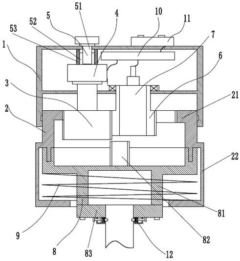
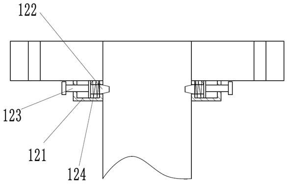
[0020] refer to figure 1 and figure 2 To further explain this application, such as figure 1 The positioning device of a smart valve positioner shown includes a fixed shell 1, an inner ring gear 2, a driving gear 3, a motor 4, a lifting adjustment mechanism 5, a connecting frame 8 and a locking mechanism 12. The fixed shell 1 realizes the installation of the present application, and the outer peripheral surface of the inner ring gear 2 has an annular flange,...


PUM


Abstract

The invention discloses a positioning device of an intelligent valve positioner. The positioning device comprises a fixed shell, an inner gear ring, a driving gear, a motor, a lifting adjusting mechanism, a connecting frame and a locking mechanism, wherein the inner gear ring is pivoted to the inner wall of the fixed shell, a positioning driven gear is pivoted to a partition plate of the fixed shell, the lifting adjusting mechanism is arranged at the top of the fixed shell, the motor is fixedly connected with a lifting block of the lifting adjusting mechanism, the driving gear is fixedly connected with the motor, the driving gear is meshed with the positioning driven gear all the time, a potentiometer fixedly arranged in a cavity of the positioning driven gear is electrically connected with a circuit board arranged in the fixed shell, the connecting frame is slidably arranged at the bottom of the inner gear ring in the axial direction, an adjusting driven gear is arranged on the connecting frame, the driving gear is meshed with a gear ring body of the inner gear ring after ascending and is meshed with the adjusting driven gear after descending, and the locking mechanism is arranged on the connecting frame and used for fixedly connecting a valve rod and the connecting frame into a whole. The positioning device is convenient to use and high in applicability.

Description

technical field [0001] The invention relates to the technical field of intelligent valve positioners, in particular to a positioning device for an intelligent valve positioner. Background technique [0002] With the advancement of industrial technology, the automation control process has become the main development trend. Intelligent valves occupy an extremely important position in industrial production. Valve positioners are the core components of intelligent valves. The positioning structure of common valve positioners is mechanical structure or Pneumatic pilot structure, mechanical structure is to drive the transmission mechanism to move through the control signal, and then make the regulating valve move, the displacement of the valve stem is fed back to the valve positioner through the mechanical device, and the valve position is transmitted to the upper system through the electrical signal to measure the position of the valve. Opening degree; the pneumatic pilot structu...

Claims


Application Information

Patent Timeline
Patent Type & Authority Applications(China)
IPC IPC(8): F16K37/00F16K31/04F16K31/05F16K31/53
CPCF16K31/043F16K31/047F16K31/05F16K31/055F16K31/53F16K31/535F16K37/0083
Inventor 宋良永
Owner WENZHOU POLYTECHNIC
Why Eureka
Try Eureka