Non-contact displacement measurement system
A displacement measurement, non-contact technology, used in measurement devices, instruments, optical devices, etc., can solve problems such as easy failure and inaccurate measurement, and achieve the effects of high sensitivity, high measurement accuracy, and good practicability
- Summary
- Abstract
- Description
- Claims
- Application Information
AI Technical Summary
Problems solved by technology
Method used
Image

Examples
Embodiment 1
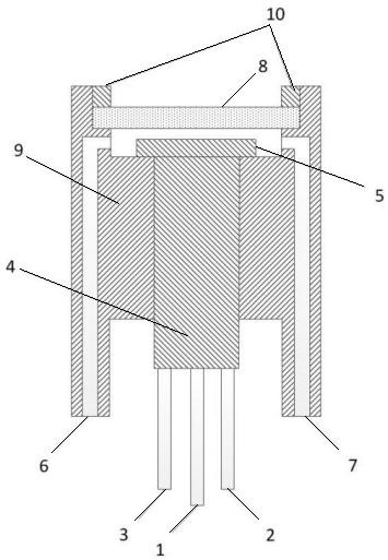
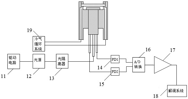
[0042] A non-contact displacement measurement system such as figure 1 , figure 2 As shown, it includes a light source module, a demodulation module, and a sensing module, and the demodulation module includes an A / D converter 16, a divider 17, and a demodulation system 18; the light source module is connected to the sensing module through a transmitting optical fiber 1 , the sensing module is connected to the photodetector through the receiving optical fiber, and the output ends of the photodetector are respectively connected to the demodulation system 18 through the A / D converter 16 and the divider 17; the sensing module includes a metal shell Body 9, sapphire glass 8, optical fiber bundle 5, optical fiber conversion connector 4, transmitting optical fiber 1, first receiving optical fiber 2, second receiving optical fiber 3; one end of the metal shell 9 is provided with a mounting groove, and the sapphire glass 8 is arranged in the mounting groove, and a cooling cavity is f...
Embodiment 2
[0047] This embodiment is optimized on the basis of embodiment 1, such as figure 2 As shown, a cooling circulation system 19 is also included, and a cooling circulation system 19 is also included. The two sides of the metal shell 9 are respectively provided with a cooling gas input channel 6 connected to an air outlet and an air inlet of the cooling circulation system 19, cooling The gas output channel 7; the cooling gas input channel 6 and the cooling gas output channel 7 communicate with the cooling cavity respectively. The cooling circulation system 19 transports cold air into the optical signal emitting part of the sensor probe through the cooling air input channel 6, and then the cold air is discharged from the cooling air output channel 7 to cool the sensor probe.
[0048] Further, it also includes a fixed pressure ring 10, and also includes a fixed pressure ring 10, a receiving seat is arranged inside the installation groove, the sapphire glass 8 is installed on the re...
Embodiment 3
[0053] This embodiment is optimized on the basis of embodiment 1 or 2, as figure 2 As shown, the light source module includes a drive circuit 11, a light source 12, and an optical isolator 13 that are sequentially connected from front to back; the light source 12 is connected to the other end of the emitting fiber 1 through an optical isolator 13; the photodetector includes PD1 photodetector 14 and PD2 photodetector 15 , the other ends of the first receiving optical fiber 2 and the second receiving optical fiber 3 are respectively connected to the PD1 photodetector 14 and PD2 photodetector 15 .
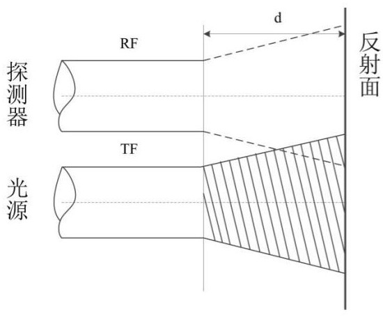
[0054]Further, the transmitting optical fiber 1 , the first receiving optical fiber 2 and the second receiving optical fiber 3 are single-mode optical fibers respectively. There are two receiving optical fibers at the receiving end of the optical fiber micro-displacement sensor, which are the first receiving optical fiber 2 and the second receiving optical fiber 3 respectively. By pe...
PUM
 Abstract
Description
Claims
Application Information
 - R&D
- Intellectual Property
- Life Sciences
- Materials
- Tech Scout
- Unparalleled Data Quality
- Higher Quality Content
- 60% Fewer Hallucinations
Browse by: Latest US Patents, China's latest patents, Technical Efficacy Thesaurus, Application Domain, Technology Topic, Popular Technical Reports.
© 2025 PatSnap. All rights reserved.Legal|Privacy policy|Modern Slavery Act Transparency Statement|Sitemap|About US| Contact US: help@patsnap.com