Rotor assembly, motor and household electrical appliance

A component and rotor technology, applied in the direction of motors, electric components, magnetic circuit rotating parts, etc., can solve the problems of limited application range of motors, low power density of motors, weak structural strength, etc., to reduce magnetic flux leakage and reduce motor costs , The effect of reducing the shape and position tolerance

Active Publication Date: 2021-06-29
GUANGDONG WELLING ELECTRIC MACHINE MFG +1
View PDF12 Cites 0 Cited by
  • Summary
  • Abstract
  • Description
  • Claims
  • Application Information

AI Technical Summary

Problems solved by technology

[0002] In the related art, the built-in rotor core is usually made of one-piece stamping of magnetically conductive material, and a large part of the magnetic flux generated by the permanent magnet passes through the fan-shaped part of the rotor core, and passes through the connecting part and the rotor sleeve part (the protrusion part and the rotor sleeve part). The shaft sleeve is integrated as a whole) for circulation, this part of the magnetic flux basically does not generate energy exchange for the motor, does not generate electromagnetic torque, resulting in a large end magnetic flux leakage phenomenon, resulting in low motor power density and high motor cost; The rotor connection part is omitted and the rotor core assembly and the rotor sleeve are integrally formed by injection molding, which can effectively reduce the magnetic flux leakage here, but the structural strength is weak, and it is not suitable for operating conditions with large torque or high speed. Motor applications are limited

Method used


Image

  • Rotor assembly, motor and household electrical appliance
  • Rotor assembly, motor and household electrical appliance
  • Rotor assembly, motor and household electrical appliance

Examples


Embodiment Construction

[0035] Embodiments of the invention are described in detail below, examples of which are illustrated in the accompanying drawings. The embodiments described below by referring to the figures are exemplary and are intended to explain the present invention and should not be construed as limiting the present invention.

[0036] Refer below Figure 1-Figure 8 Rotor assemblies provided according to some embodiments of the invention are described.

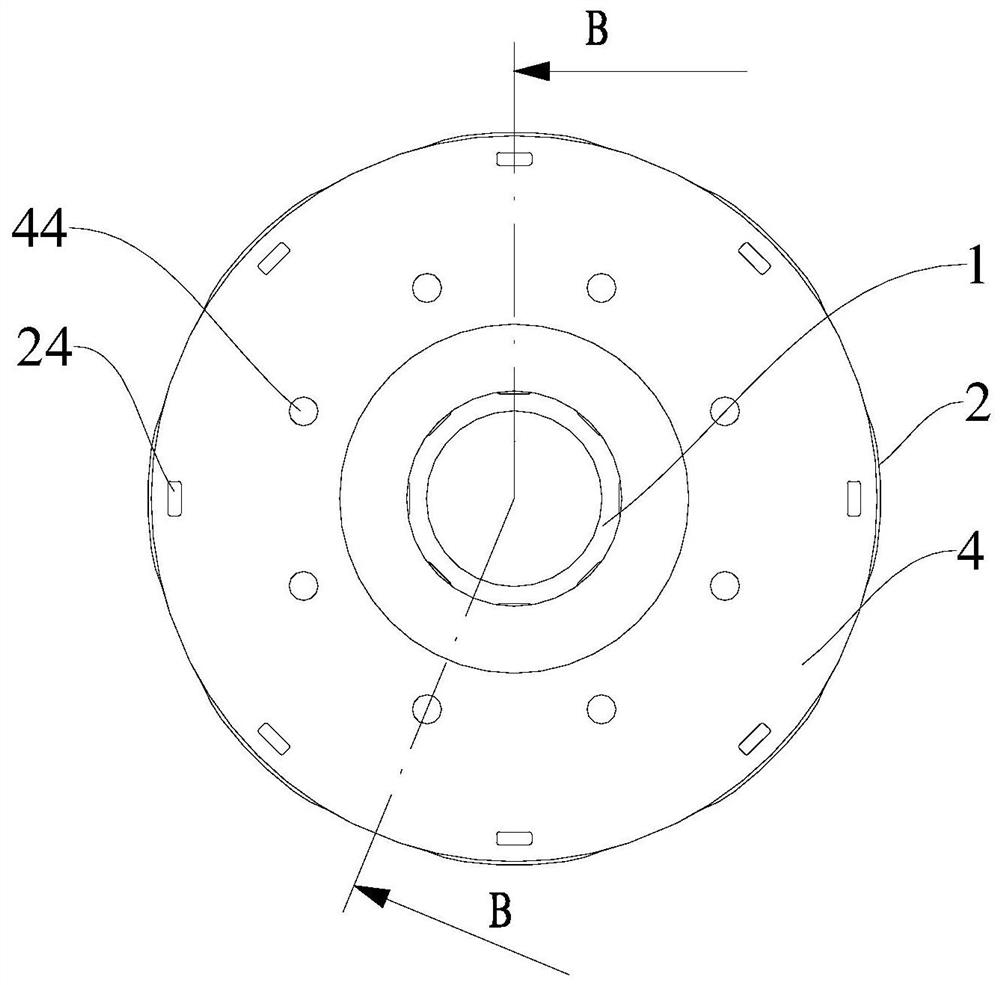
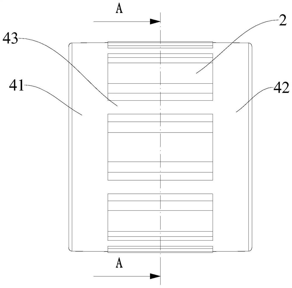
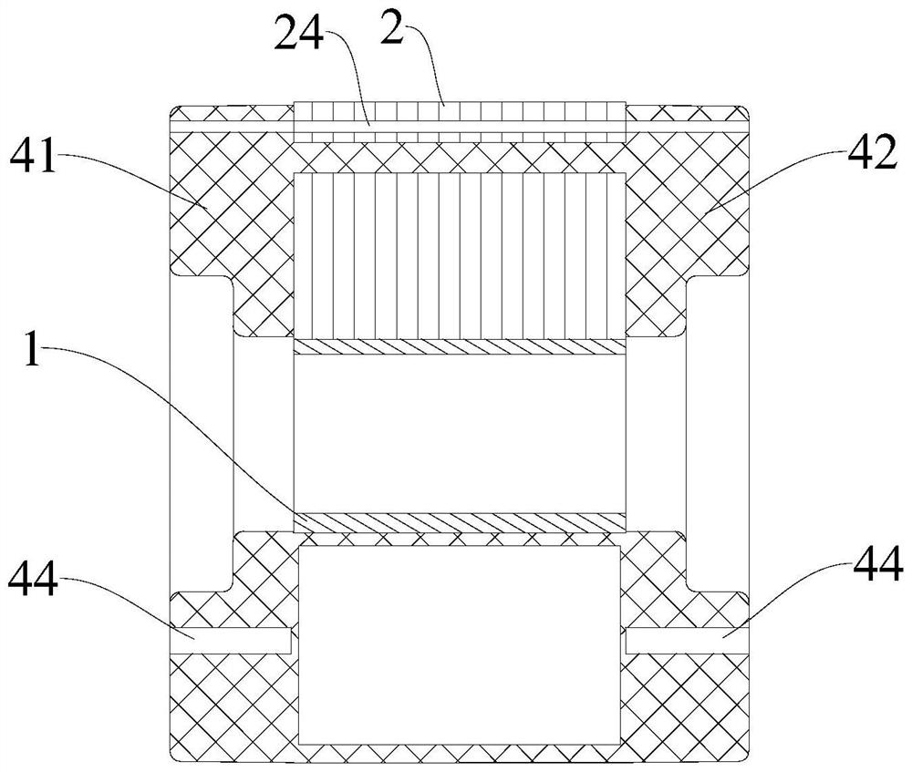
[0037] Such as Figure 1-Figure 4 As shown, the rotor assembly according to the embodiment of the present invention includes a shaft sleeve 1, a reinforcing boss 14, a rotor core 2 and a permanent magnet 3, wherein the shaft sleeve 1 is generally cylindrical, and the reinforcing boss 14, the rotor core 2 and The permanent magnets 3 are all connected to the sleeve 1, and the reinforcement boss 14, the rotor core 2 and the permanent magnet 3 are all located on the peripheral side of the sleeve 1, and the reinforcement boss 14 extends alo...


PUM


Abstract

The invention discloses a rotor assembly, a motor and a household electrical appliance, the rotor assembly comprises a shaft sleeve, a plurality of reinforcing bosses, a plurality of rotor cores and a plurality of permanent magnets, the shaft sleeve is made of a non-magnetic material, the plurality of reinforcing bosses are arranged at intervals along the circumferential direction of the shaft sleeve, and the plurality of rotor cores are arranged at intervals in the circumferential direction of the shaft sleeve. The plurality of rotor cores are arranged at intervals in the circumferential direction of the shaft sleeve, a mounting groove is formed between every two adjacent rotor cores, each rotor core comprises a protruding part, the protruding parts are connected with the shaft sleeve, a spacing distance is formed between any two protruding parts, the permanent magnets are arranged in the mounting grooves, and the permanent magnets are arranged in the mounting grooves. The plurality of permanent magnets and the plurality of rotor cores are sequentially and alternately arranged in the circumferential direction of the shaft sleeve. According to the rotor assembly provided by the embodiment of the invention, the magnetic circuit magnetic flux flowing through the rotor iron core and the shaft sleeve is effectively limited, so that the magnetic leakage phenomenon of the end part of the rotor is effectively reduced, the motor power density is improved, and the motor cost is reduced.

Description

technical field [0001] The invention relates to the technical field of motors, in particular to a rotor assembly, a motor and household appliances. Background technique [0002] In the related art, the built-in rotor core is usually made of one-piece stamping of magnetically conductive material, and a large part of the magnetic flux generated by the permanent magnet passes through the fan-shaped part of the rotor core, and passes through the connecting part and the rotor sleeve part (the protrusion part and the rotor sleeve part). The shaft sleeve is integrated as a whole) for circulation, this part of the magnetic flux basically does not generate energy exchange for the motor, does not generate electromagnetic torque, resulting in a large end magnetic flux leakage phenomenon, resulting in low motor power density and high motor cost; The rotor connection part is omitted and the rotor core assembly and the rotor sleeve are integrally formed by injection molding, which can eff...

Claims


Application Information

Patent Timeline
Patent Type & Authority Applications(China)
IPC IPC(8): H02K1/27
CPCH02K1/276Y02T10/64
Inventor 张婷婷邵非非李文瑞李虎
Owner GUANGDONG WELLING ELECTRIC MACHINE MFG
Why Eureka
Try Eureka