
A kind of preparation method of thin-walled part

A technology for thin-walled parts and blanks, which is applied in the field of thin-walled parts preparation, can solve the problems of self-heavy, deformation, and low product yield of thin-walled pads, and can eliminate defects, improve wear resistance, and achieve stable and reliable quality. Effect

Active Publication Date: 2022-06-17
XIAN COAL MINING MACHINERY
View PDF12 Cites 0 Cited by
  • Summary
  • Abstract
  • Description
  • Claims
  • Application Information

AI Technical Summary

Problems solved by technology

[0003] Since thin-walled parts require carburizing on both ends, in the prior art, since thin-walled parts are thin-walled and easily deformed structures, a single thin-walled part is often used to carburize in a carburizing furnace by hanging across a cross bar, but thin-walled The circumferential direction of the part is perpendicular to the direction of the crossbar and parallel to the direction of gravity, and the thin-walled pad is self-heavy. After carburizing under high temperature conditions for a long time, the thin-walled parts are superimposed by self-weight and high temperature creep, and the deformation is basically uncontrollable. 1. During the quenching process, due to the superposition of tissue stress and thermal stress, great deformation will also occur, resulting in a low product yield, generally only 5% to 10%.

Method used


Image

  • A kind of preparation method of thin-walled part
  • A kind of preparation method of thin-walled part
  • A kind of preparation method of thin-walled part

Examples


Embodiment 1

[0043] This embodiment includes the following steps:

[0044] Step 1: Forging: Die forging and punching are performed in sequence after heating the steel raw material to obtain a cylindrical forging billet; the material of the steel raw material is 18Cr2Ni4WA; the initial forging temperature in the die forging process is 1180 ° C, and the final forging temperature is 850℃;

[0045] Step 2, pre-heat treatment: normalizing and high temperature tempering are carried out successively to the cylindrical forging blank obtained in step 1 to obtain a blank; the temperature of the normalizing is 920 ℃, and the temperature of the high temperature tempering is 670 ℃;

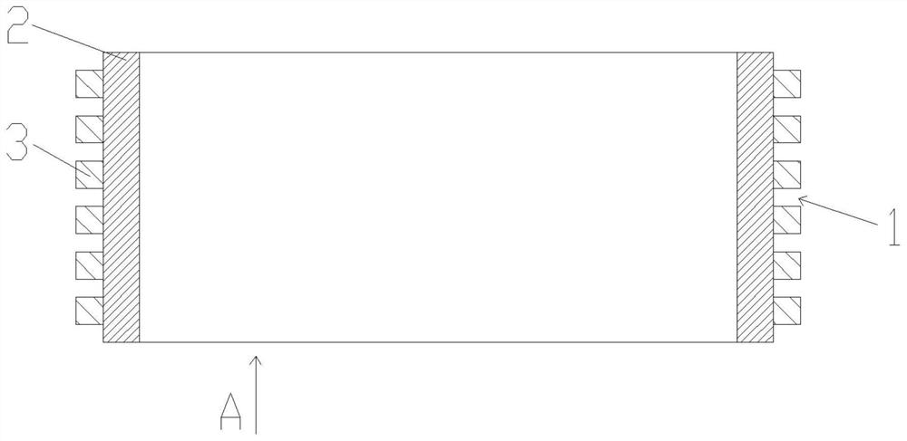
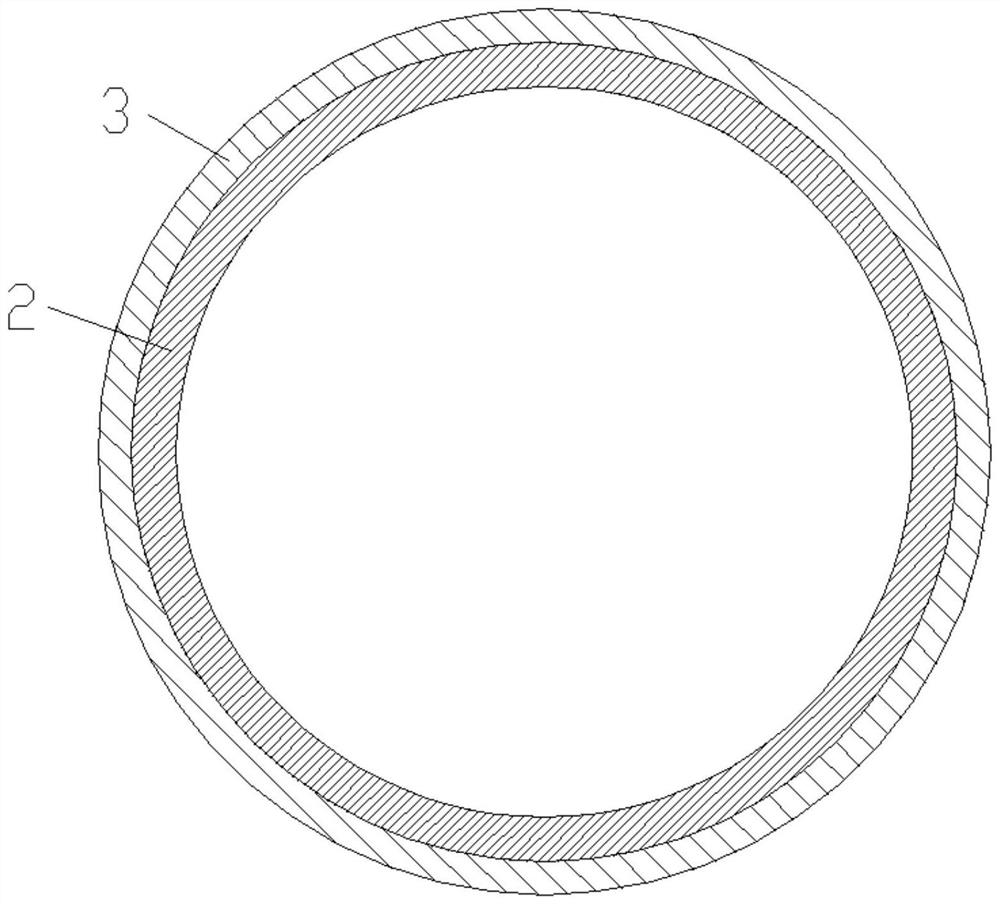
[0046] Step 3: Rough machining: rough machining the blank obtained in step 2 to obtain a blank; the rough machining process is: opening a plurality of annular grooves on the outer surface of the blank in a direction perpendicular to the height of the blank; the The blank consists of a support structure and a plurality of ...

Embodiment 2

[0055] This embodiment includes the following steps:

[0056] Step 1: Forging: Die forging and punching are performed in sequence after heating the steel raw material to obtain a cylindrical forging billet; the material of the steel raw material is 20CrNi2Mo; the initial forging temperature in the die forging process is 1140 ° C, and the final forging temperature is 880℃;

[0057] Step 2, pre-heat treatment: normalizing and high temperature tempering are carried out successively to the cylindrical forging blank obtained in step 1 to obtain a blank; the temperature of the normalizing is 950 ℃, and the temperature of the high temperature tempering is 640 ℃;

[0058] Step 3: Rough machining: rough machining the blank obtained in step 2 to obtain a blank; the rough machining process is: opening a plurality of annular grooves on the outer surface of the blank in a direction perpendicular to the height of the blank; the The blank is composed of a support structure and a plurality o...

Embodiment 3

[0067] This embodiment includes the following steps:

[0068] Step 1. Forging: Die forging and punching are performed in sequence after heating the steel raw material to obtain a cylindrical forging blank; the material of the steel raw material is 12Cr2Ni4A; the initial forging temperature in the die forging process is 1160 ° C, and the final forging temperature is 12Cr2Ni4A. 860℃;

[0069] Step 2, pre-heat treatment: normalizing and high temperature tempering are carried out successively to the cylindrical forging blank obtained in step 1 to obtain a blank; the temperature of the normalizing is 920 ℃, and the temperature of the high temperature tempering is 670 ℃;

[0070] Step 3: Rough machining: rough machining the blank obtained in step 2 to obtain a blank; the rough machining process is: opening a plurality of annular grooves on the outer surface of the blank in a direction perpendicular to the height of the blank; the The blank is composed of a support structure and a p...


PUM

PropertyMeasurementUnit
depthaaaaaaaaaa
heightaaaaaaaaaa
heightaaaaaaaaaa

Abstract

The invention discloses a preparation method of a thin-walled part. The method comprises the following steps: 1. forging; 2. pre-heat treatment; 3. rough processing; 4. deep carburizing; 5. high-temperature tempering; ; 7. Quenching; 8. Low temperature tempering; 9. Finishing to obtain thin-walled parts. The present invention realizes simultaneous carburizing on both ends of the thin-walled part in the thickness direction by opening a plurality of annular grooves on the outer surface of the blank, reduces thermal stress deformation during carburizing, and prevents excessive deformation of the thin-walled part from causing cracks, making the The deformation is identical, which ensures that thin-walled parts will not be deformed by thermal stress due to high temperature creep and self-weight, and makes the surface hardness of thin-walled parts and the thickness of hardened layer uniform, thereby improving the wear resistance of thin-walled parts and ensuring thin-walled parts The quality of the parts is stable and reliable, realizing the preparation of multiple thin-walled parts with uniform performance at one time.

Description

technical field [0001] The invention belongs to the technical field of thin-walled parts, and in particular relates to a preparation method of thin-walled parts. Background technique [0002] The planetary deceleration structure is used in the transmission mechanism of the shearer to transmit torque and achieve the purpose of deceleration. Its structure is divided into two-stage planetary deceleration structure, and the two-stage planetary deceleration structure has a certain axial displacement and has a great impact. In order to solve this problem, Wear-resistant and impact-reducing thin-walled parts are designed between the two-stage planetary deceleration structure. In order to ensure service characteristics, high-quality carburized steel is selected for deep carburizing and quenching treatment to meet the requirements of high wear resistance on the surface and good toughness in the core. technical features. [0003] Since thin-walled parts require carburizing on both en...

Claims


Application Information

Patent Timeline
Patent Type & Authority Patents(China)
IPC IPC(8): B23P15/00C21D1/18C21D1/28C21D6/00C21D9/00C23C8/02C23C8/22C23F17/00
CPCB23P15/00C21D1/28C21D1/18C23C8/22C23C8/02C21D9/0068C23F17/00C21D6/004C21D6/005C21D6/008C21D2261/00C21D2211/008
Inventor 周晓红权振林朱科史华丽侯军张维林
Owner XIAN COAL MINING MACHINERY
Learn More