Construction site assembled steel pipe threaded hole fluting apparatus for high-end equipment manufacturing

A technology for construction sites and slotting equipment, which is applied in the direction of manufacturing tools, metal processing equipment, drilling/drilling equipment, etc., which can solve the problems of low processing efficiency, long processing time, and large manpower consumption to achieve precise slotting , keep clean effect

Active Publication Date: 2021-07-02
深圳市富建建设集团有限公司
View PDF6 Cites 2 Cited by
  • Summary
  • Abstract
  • Description
  • Claims
  • Application Information

AI Technical Summary

Problems solved by technology

[0004] In order to overcome the shortcomings of long processing time, large manpower consumption, and low processing efficiency, the technical problem of the present invention is to provide a high-end equipment manufacturing site-assembled steel pipe threaded hole slotting equipment with high processing efficiency

Method used


Image

  • Construction site assembled steel pipe threaded hole fluting apparatus for high-end equipment manufacturing
  • Construction site assembled steel pipe threaded hole fluting apparatus for high-end equipment manufacturing
  • Construction site assembled steel pipe threaded hole fluting apparatus for high-end equipment manufacturing

Examples


Embodiment 1

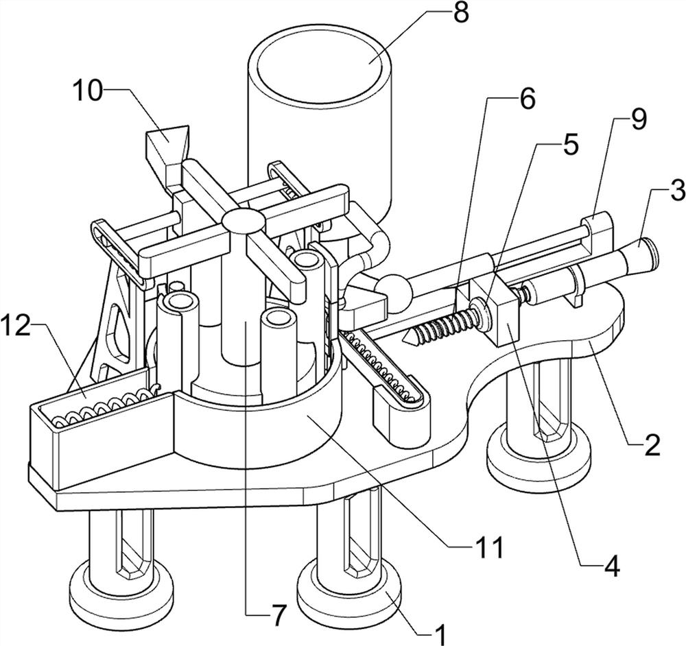
[0067] A high-end equipment manufacturing site assembly steel pipe threaded hole slotting equipment, such as figure 1 As shown, it includes a base 1, a mounting plate 2, a cylinder 3, a first connecting plate 4, a brushless motor 5, a tapping drill 6, a transport mechanism 7 and a cooling mechanism 8, which is provided with three bases 1, and the top of the base 1 There is a mounting plate 2 between them, and the right part of the mounting plate 2 is provided with a cylinder 3, the cylinder 3 is provided with a first connecting plate 4, the first connecting plate 4 is provided with a brushless motor 5, and the brushless motor 5 is provided with a tapping Wire drill bit 6, mounting plate 2 left parts are provided with transportation mechanism 7, and mounting plate 2 right rear parts are provided with cooling mechanism 8.

[0068] When people need to slot the material, they place the material on the mounting plate 2, and then they start the cylinder 3 and the brushless motor 5, ...

Embodiment 2

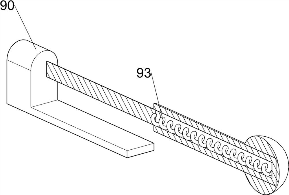
[0070] On the basis of Example 1, such as Figure 2 to Figure 8 As shown, the transportation mechanism 7 includes a rack 70, a rotating shaft 71, a gear 72, a one-way clutch 73 and a sheave 74, the first connecting plate 4 is provided with a rack 70, and the left part of the mounting plate 2 is rotationally connected with a rotating shaft 71 The bottom of the rotating shaft 71 is provided with a gear 72, the gear 72 cooperates with the rack 70, the bottom of the rotating shaft 71 is provided with a one-way clutch 73, and the rotating shaft 71 is provided with a sheave 74.

[0071] When people need to slot the material, people place the material on the left part of the mounting plate 2 to contact the sheave 74, and then people start the cylinder 3 and the brushless motor 5, and the cylinder 3 drives the first connecting plate 4 and the brushless motor 5. The tapping bit 6 and the rack 70 move to the left, the rack 70 meshes with the gear 72, drives the gear 72, the one-way clutch...


PUM


Abstract

The invention relates to fluting apparatuses, in particular to a construction site assembled steel pipe threaded hole fluting apparatus for high-end equipment manufacturing. The technical problem to be solved is to provide the construction site assembled steel pipe threaded hole fluting apparatus for high-end equipment manufacturing, which is higher in machining efficiency. According to the technical scheme, the construction site assembled steel pipe threaded hole fluting apparatus for high-end equipment manufacturing comprises three bases, a mounting plate arranged between the tops of the bases, an air cylinder arranged at one side of the mounting plate, a first connecting plate arranged on the air cylinder, a brushless motor arranged on the first connecting plate, a tapping drill bit arranged on the brushless motor, a conveying mechanism arranged at one side of the mounting plate, and a cooling mechanism arranged at one side of the mounting plate. Through the action of a feeding mechanism, automatic feeding of materials can be achieved.

Description

technical field [0001] The invention relates to a slotting device, in particular to a slotting device for threaded holes of steel pipes assembled on construction sites for high-end equipment manufacturing. Background technique [0002] The steel pipe has a hollow section, the length of which is much longer than the diameter or circumference of the steel, and the steel pipe is not only used for conveying fluid and powdery solids, exchanging heat energy, making mechanical parts and containers, but also an economical steel. The use of steel pipes to manufacture highway bridges can not only save steel and simplify construction, but also greatly reduce the area of ​​the protective layer, saving investment and maintenance costs. [0003] However, the length of the steel pipe is long, the hardness is high, the processing of the steel pipe is more difficult, the processing time is long, the labor time is large, and the processing efficiency is low. Therefore, a high-end equipment ma...

Claims


Application Information

Patent Timeline
Patent Type & Authority Applications(China)
IPC IPC(8): B23Q7/00B23Q3/00B23Q11/00B23B41/00
CPCB23Q7/00B23Q3/00B23Q11/0042B23B41/00Y02P70/10
Inventor 欧志明
Owner 深圳市富建建设集团有限公司
Why Eureka
Try Eureka