Transient effect inhibitor for optical fiber amplifier in WDM system

A fiber amplifier and suppressor technology, applied in the field of optical communication, can solve problems such as adjusting operating parameters and complex structure of fiber amplifiers

Inactive Publication Date: 2003-12-10
SAMSUNG ELECTRONICS CO LTD
View PDF3 Cites 0 Cited by
  • Summary
  • Abstract
  • Description
  • Claims
  • Application Information

AI Technical Summary

Problems solved by technology

The previous optical method is effective for suppressing this transient effect, but it has the disadvantages of complex structure of the fiber amplifier and difficulty in adjusting the operating parameters a

Method used


Image

  • Transient effect inhibitor for optical fiber amplifier in WDM system
  • Transient effect inhibitor for optical fiber amplifier in WDM system
  • Transient effect inhibitor for optical fiber amplifier in WDM system

Examples


Embodiment Construction

[0018] Preferred embodiments of the present invention will be described below with reference to the accompanying drawings. In the following description, well-known functions and constructions are not described in detail since they would obscure the invention in unnecessary detail.

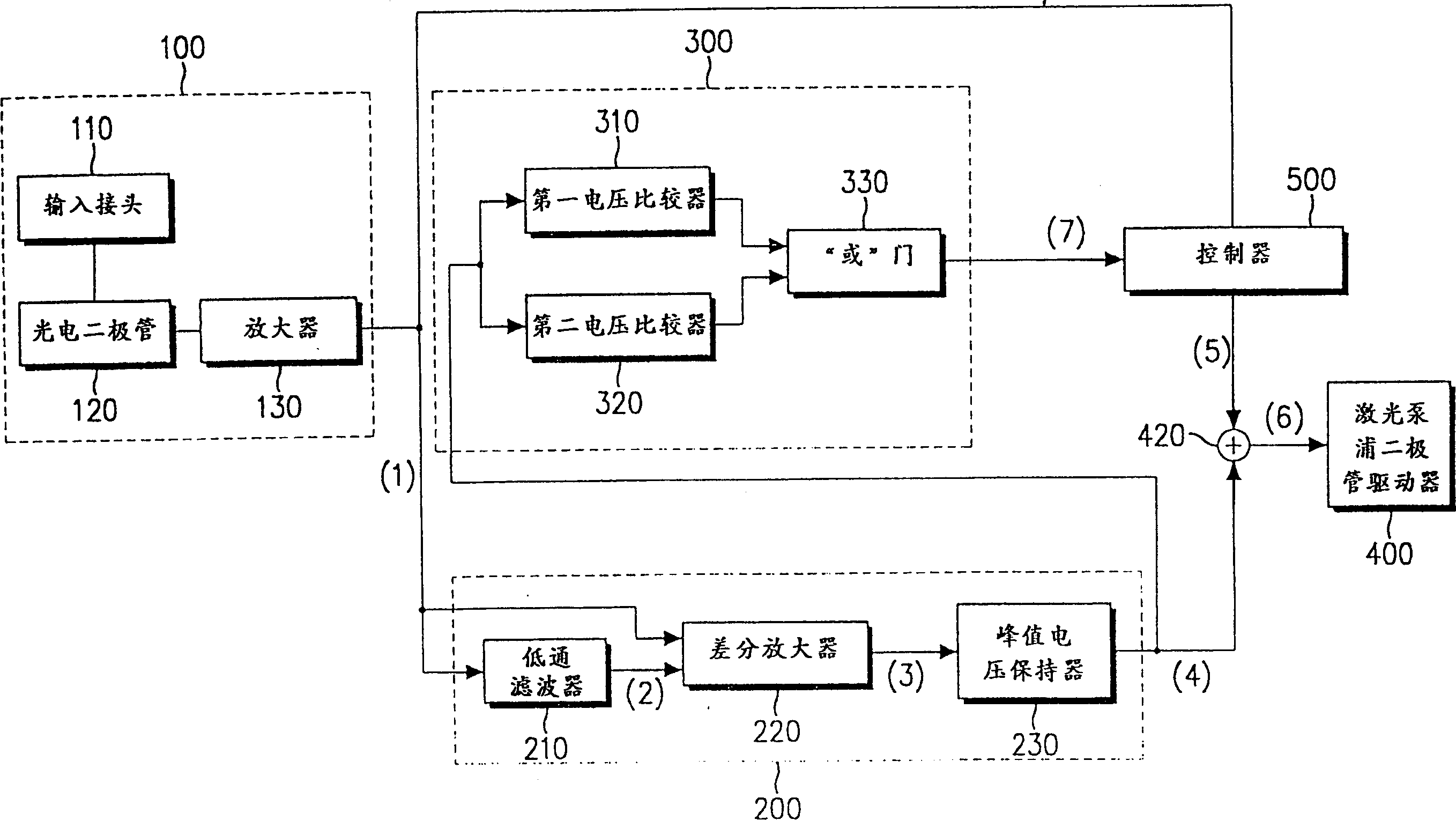
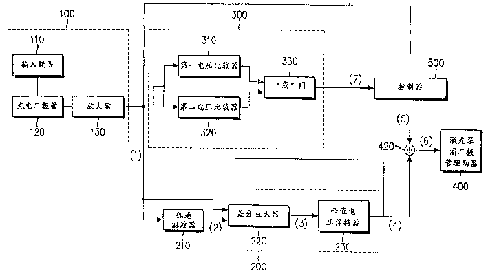
[0019] refer to figure 1 , The transient effect suppression device according to the preferred embodiment of the present invention includes an input sensor 100 , a transient effect suppressor 200 , a voltage comparator 300 , a laser pump diode driver 400 and a controller 500 .

[0020] 1. Input sensor

[0021] The input sensor 100 converts the optical signal applied to the input of the fiber amplifier into an electrical signal. The input sensor 100 includes an input connector 110 , a photodiode 120 and an amplifier 130 .

[0022] The input connector 110 splits off a portion of the input optical signal at a predetermined ratio. The photodiode 120 converts an optical signal incident from the input...


PUM


Abstract

A device for suppressing the transient effect of an optical fiber amplifier in a WDM system includes an input sensor which converts an input optical signal to an electrical signal; a transient effect suppresser for holding the electrical signal received from the input sensor for a predetermined time and for outputting the delayed signal in the form of pulses that are proportional to the variation of the number of channels; a voltage comparator for comparing the predetermined reference voltages with the amplitude of the pulses received from the transient effect suppresser and for outputting a trigger signal when the channel number is changed; a pump laser diode driver for supplying a driving voltage to a pump laser diode in response to the received pump indication signal; and, a controller for outputting the pump indication signal corresponding to the changed channel number in response to the trigger signal.

Description

technical field [0001] The present invention generally relates to optical communication in a WDM (Wavelength Division Multiplexing) system, and specifically relates to a device for suppressing transient effects of remaining channels caused by changes in the number of channels. Background technique [0002] Using optical fibers, WDM systems simultaneously transmit optical signals on multiple channels through different wavelengths to achieve high-speed transmission of large amounts of data. [0003] WDM systems are equipped with optical fiber amplifiers for amplifying optical signals without optical-to-electrical conversion. Fiber amplifiers rely on the amplification of optical fibers doped with rare earth elements (eg, bait) to amplify optical signals, details of which are disclosed in US Patent No. 5,218,608, US Patent No. 5,245,690, and US Patent No. 5,467,218. The number, output power and SNR (Signal to Noise Ratio) of each channel transmitted over random distances needs ...

Claims


Application Information

Patent Timeline
IPC IPC(8): H01S3/10G02B6/00H01S3/06H01S3/067H01S3/094H01S3/0941H01S3/102H04B10/07H04B10/2507H04B10/29H04B10/293H04B10/296H04B10/564H04B10/572H04J14/00H04J14/02
CPCH01S3/1022G02B6/00
Inventor 崔道仁辛哄硕
Owner SAMSUNG ELECTRONICS CO LTD
Why Eureka
Try Eureka