Control system of optical fiber amplifier

A fiber amplifier and control system technology, applied in the field of optical communication, can solve problems such as unstable optical power detection value, affecting gain stability, and insufficient detection accuracy, and achieves the effects of simple structure, stable output power, and maintenance of detection accuracy

Inactive Publication Date: 2019-03-08
O NET COMM (SHENZHEN) LTD
View PDF4 Cites 5 Cited by
  • Summary
  • Abstract
  • Description
  • Claims
  • Application Information

AI Technical Summary

Problems solved by technology

[0005] The technical problem to be solved by the present invention is to provide a control system of an optical fiber amplifier for the above-mentioned defects of the prior art, to overcome the complex transient response design structure of the optical fiber amplifier in the existing optical fiber communication system, and to cause insufficient detection accuracy, The optical power detection value is unstable, which affects the normal working performance such as gain stability and output power stability

Method used


Image

  • Control system of optical fiber amplifier
  • Control system of optical fiber amplifier
  • Control system of optical fiber amplifier

Examples


Embodiment Construction

[0031] Now in conjunction with the accompanying drawings, the preferred embodiments of the present invention will be described in detail.

[0032] Such as Figure 1 to Figure 3 As shown, the present invention provides a preferred embodiment of a control system for an optical fiber amplifier.

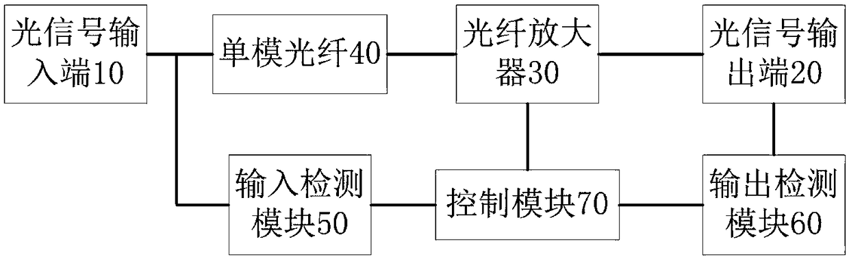
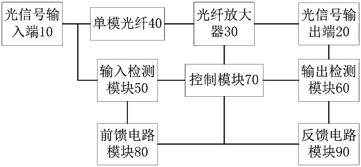
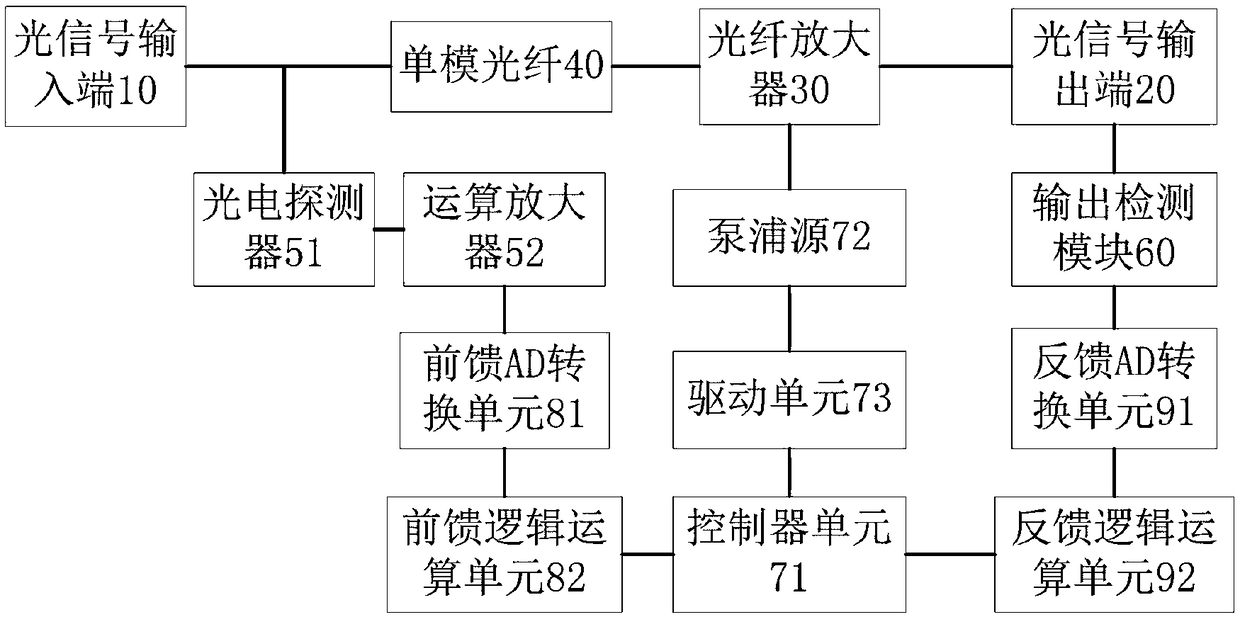
[0033] The control system of the optical fiber amplifier includes an optical signal input port 10 for inputting an optical signal, an optical signal output port 20 for outputting an optical signal, and an optical fiber amplifier 30 for amplifying the input optical signal, and also includes:

[0034] A single-mode optical fiber 40 with a length of L is located between the optical signal input end 10 and the input end of the optical fiber amplifier 30, wherein L is a constant greater than zero;

[0035] Input detection module 50, the input end of input detection module 50 is arranged between optical signal input end 10 and single-mode optical fiber 40, is used for detecting the input opti...


PUM


Abstract

The invention relates to the field of optical communication, in particular to a control system of an optical fiber amplifier. The control system comprises an optical signal input end, an optical signal output end and an optical fiber amplifier, and further comprises a single-mode optical fiber with a length of L, an input detection module, an output detection module and a control module, wherein the single-mode optical fiber is arranged between the optical signal input end and the input end of the optical fiber amplifier, and L is a constant greater than zero; the input end of the input detection module is arranged between the optical signal input end and the single-mode optical fiber; the input end of the output detection module is arranged between the output end of the optical fiber amplifier and the optical signal output end; and the control module is respectively connected with the output end of the input detection module, the output end of the output detection module and the control end of the optical fiber amplifier and controls the optical fiber amplifier to work according to the input power and the output optical power of optical signals. By arranging the single-mode optical fiber with the length of L between the optical signal input end and the input end of the optical fiber amplifier, the time for transmitting the optical signals to the input end of the optical fiberamplifier is extended, the transient response control of the optical fiber amplifier is optimized, and relevant parameters are kept stable.

Description

technical field [0001] The invention relates to the field of optical communication, in particular to a control system of an optical fiber amplifier. Background technique [0002] In optical fiber communication systems, fiber amplifiers, especially erbium-doped fiber amplifiers, have become one of the core components of the system, and play an irreplaceable role in the relay regeneration and amplification of optical signals. At the same time, the mature use of dense wavelength division multiplexing technology (DWDM) transmits multiple wavelengths of light in one optical fiber as different channels without interfering with each other, which greatly expands and enriches the communication efficiency and communication efficiency of optical fibers. information capacity. [0003] In the DWDM communication system, the number of wavelengths transmitted in an optical fiber is variable according to needs, that is, the wavelength channels can be increased or decreased. In the process ...

Claims


Application Information

Patent Timeline
Patent Type & Authority Applications(China)
IPC IPC(8): H01S3/067H01S3/091H01S3/13H01S3/131
CPCH01S3/06754H01S3/0912H01S3/1301H01S3/1305H01S3/1312
Inventor 熊奇
Owner O NET COMM (SHENZHEN) LTD
Why Eureka
Try Eureka