[0084] The present invention will be further described below in conjunction with embodiment and accompanying drawing.
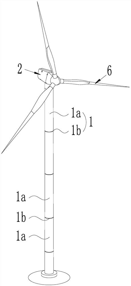
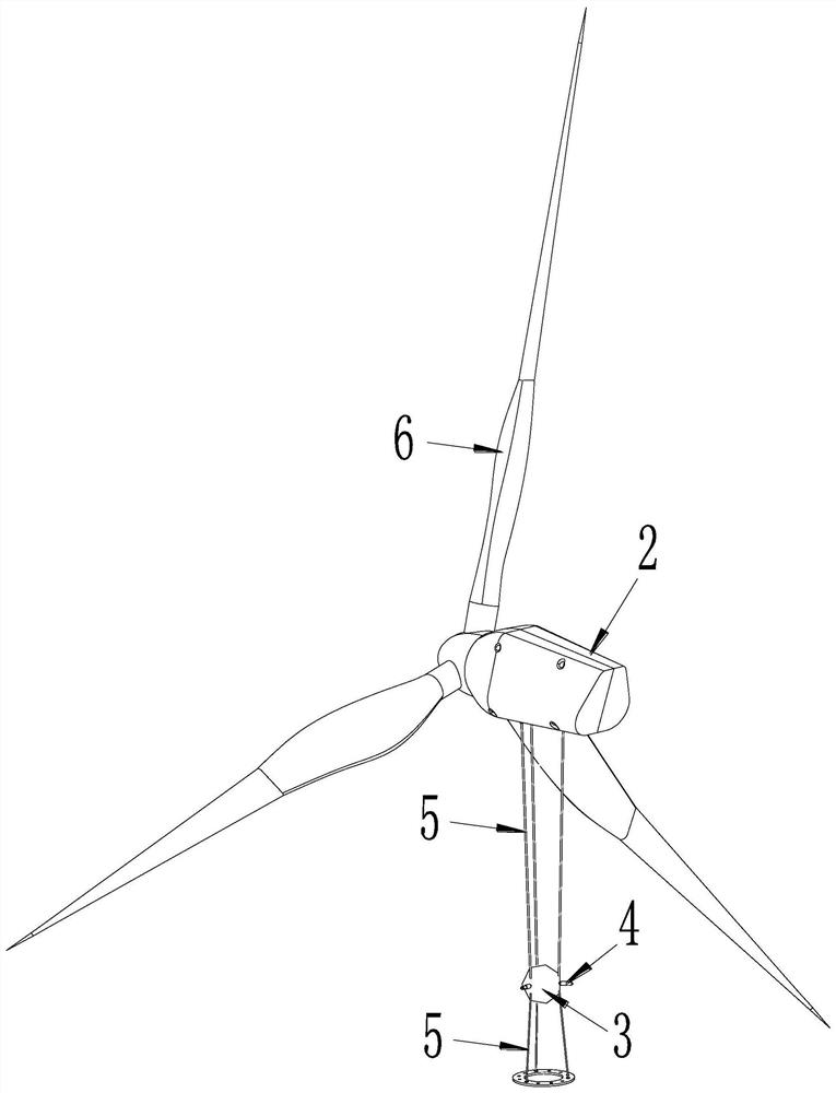
[0085] like figure 1 and figure 2 As shown, a prestressed tuned mass damper installation method based on parameter design calculation, the wind turbine tower structure includes a tower 1 and a nacelle 2 installed on the top of the tower, the blade 6 is rotatably installed on the nacelle 2, the tower The frame 1 is composed of several tower tubes 1a which are sequentially connected by flanges 1b. The prestressed tuned mass damper includes a mass block 3 that is hung between the top of the tower (i.e. the nacelle 2) and the flange 1b closest to the top of the tower through a prestressed cable 5, and several Dampers 4, both ends of each damper 4 are elastically supported between the outer wall of the mass block 3 and the inner wall of the corresponding tower 1a.
[0086] The mass block 3 is connected to the wall of the tower 1a through several dampers 4 that equally divide the circumference, and then the inertial force generated by the mass block 3 is used to dissipate energy, and the frequency of the mass block 3 itself is double-tuned by prestress and suspension height. In the service environment, when the horizontal amplitude of the top of the tower 1 is small, the mass block 3 will quickly generate corresponding horizontal vibration under the action of the inertial force, and under the action of the prestressed cable, the inertial force generated by the movement of the mass block 3 will react on the structure itself , resulting in a damping effect.
[0087] Further, the dampers 4 are all preferably viscous dampers, which can not only provide stable and reliable additional damping, but also play a guiding and limiting role, and can also be used as a composite damping element to avoid the occurrence of large swing angles. To solve the problem of frequency misalignment, realize the double tuning function of the ring mass under large vibration.
[0088] See Figure 1-Figure 4 , the installation method of the prestressed tuned mass damper is carried out according to the following steps:
[0089] S1. Calculate and obtain the parameters of the wind turbine tower structure.
[0090] Specifically, step S1 includes the following steps:
[0091] S11. Simplify the wind turbine tower structure in reality into an equivalent single-degree-of-freedom system dynamics model of the wind turbine tower structure: simplify the wind turbine tower mechanism into a cantilever beam structure, and take the tower structure of the wind turbine tower structure 1 The center point of the bottom surface is the origin of the coordinate system, the vertical direction of the tower 1 is the z axis, the downwind direction of the wind turbine is the x axis, and the crosswind direction of the wind turbine is the y axis (the crosswind direction is along the horizontal direction and perpendicular to the downwind direction, Therefore, the y-axis is perpendicular to the x-axis on the horizontal plane), the lumped mass of the nacelle 2 and the blade 6 at the top of the tower 1 is M, the total height of the tower 1 is H, the mass density of the tower 1 is m(z), the tower The bending stiffness EI(z) of frame 1 varies along the z-axis direction.
[0092] S12. Obtain the shape function of the first-order vibration of the tower 1 according to step S11:
[0093]
[0094] In formula (1), t represents time, and the unit of t is s, x(z, t) represents the displacement of z section at time t, and x(H, t) represents the displacement of tower top at time t;
[0095] According to the deflection of the free end of the cantilever beam under the concentrated load of material mechanics, it can be known that:
[0096]
[0097] In the formula, P represents the concentrated force, and the unit is N, and EI represents the bending stiffness of the tower section;
[0098] Substituting formula (2) into formula (1) can get:
[0099]
[0100] Step 13, calculate the generalized mass m of the wind turbine tower structure s and generalized stiffness k s :
[0101] According to the generalized distribution flexibility theory, the generalized mass m s and generalized stiffness k s Can be expressed as:
[0102]
[0103] In formula (4), the generalized mass m s The unit is kg, the generalized stiffness k s The unit is N/m, m(z) represents the distributed mass of the wind turbine tower along the z-axis direction, the unit of m(z) is kg/m, g represents the acceleration of gravity, and the unit of g is m/s 2 , Indicates the value of the shape function at the top of the tower, and its value is 1.
[0104] S2. According to the obtained parameters of the wind turbine tower structure, calculate and obtain the parameters of the prestressed tuned mass damper.
[0105] Specifically, step S2 includes the following steps:
[0106] Step S21, calculating the mass m of the prestressed tuned mass damper d :
[0107] m d =am s (5)
[0108] In formula (5), a is an intermediate parameter, and the value range of a is 1% to 3%. It should be pointed out that the value range of a is obtained based on experiments, and the mass m d The unit is kg;
[0109] Step S22, calculate the suspension height h' of the prestressed tuned mass damper:
[0110] h'=bh (6)
[0111] In formula (6), b is an intermediate parameter, and the value range of b is 1/4 to 1/2. It should be pointed out that the value range of b is obtained based on field experience, and the suspension height h' represents the prestress The distance from the mass block of the tuning mass damper to the top of the tower, the unit of h' is m, h represents the distance from the flange closest to the top of the tower to the top of the tower, and the unit of h is m;
[0112] Step S23, calculating the fundamental circular frequency ω of the prestressed tuned mass damper d :
[0113] See Figure 4 , according to the structural dynamics principle and the dynamic analysis model of the wind turbine tower and the prestressed tuned mass damper, the motion equation of the system is obtained:
[0114]
[0115] In formula (7), c s Indicates the damping coefficient of the wind turbine tower structure. For steel low-damping towers, in order to simplify the calculation, c is usually taken s =0, F(t) is external load, c d Indicates the damping coefficient, x s Tower top displacement, x d Displacement of mass block, k d Indicates the lateral stiffness of the damper;
[0116] According to formula (7) and the principle of structural dynamics, the basic circular frequency ω of the wind turbine tower after installing the prestressed tuned mass damper s Can be expressed as:
[0117]
[0118] In formula (8), ω s The unit is rad/s;
[0119] According to formula (7) and the principle of structural dynamics, the basic circular frequency ω of the prestressed tuned mass damper d Can be expressed as:
[0120]
[0121] In formula (9), ω d The unit is rad/s;
[0122] Step S24, calculate the prestress value f of the prestress cable:
[0123] Assuming that the form of F(t) is a sinusoidal load, it can be expressed as:
[0124] F(t)=P 0 sin ωt (10)
[0125] In formula (10), P 0 Indicates the sinusoidal load amplitude, ω is the load frequency;
[0126] Substitute formula (10) into formula (7), solve the motion equation of the system, and obtain the dynamic amplification factor η of the system:
[0127]
[0128] In formula (11), β represents the load frequency ω and the basic circular frequency ω of the wind turbine tower after installing the prestressed tuned mass damper s The ratio of , μ represents the fundamental circular frequency ω of the prestressed tuned mass damper d and the basic circular frequency ω of the wind turbine tower after installing the prestressed tuned mass s The ratio of , α and γ both represent the ratio of damping parameters, and its expression is:
[0129]
[0130] Combining the existing theory of tuned liquid dampers and the principles of structural dynamics, the optimal frequency ratio μ opt The expression of is as follows:
[0131]
[0132] due to μ opt = ω d /ω s , so:
[0133]
[0134] Substituting formulas (8) and (9) into formula (14), the prestress f of the prestress tuned mass damper is obtained as:
[0135]
[0136] In formula (15), the unit of prestress f is N;
[0137] Step 25, calculate the viscous damping coefficient c of each damper d :
[0138] Combined with the existing theory of tuned liquid damper and formula (11), the following expression is obtained:
[0139]
[0140] In formula (16), η and β represent the power amplification factor and damping ratio, respectively, and β M and beta N is the branch point frequency ratio, and its expression is:
[0141]
[0142] In formula (17), μ represents the frequency ratio, and both γ and α represent the tuning parameter ratio;
[0143] According to formulas (16) and (17), we can get:
[0144]
[0145] In formula (18), ζ=c d /(m d ω s ), by solving formula (18), we can get:
[0146]
[0147] In formula (19), the viscous damping coefficient c of each damper d The unit is N/m/s.
[0148] S3. Select the corresponding prestressed tuned mass damper, and install the prestressed tuned mass damper on the wind turbine tower. Specifically, based on the parameters of the basic wind turbine tower structure, the mass m of the prestressed tuned mass damper is determined d , suspension height h’, basic circular frequency ω d , the prestress value f of the prestressed cable and the viscous damping coefficient c of each damper d , installing the prestressed tuned mass damper on the wind turbine tower can have an excellent damping effect on the wind turbine tower structure.
[0149] Finally, it should be noted that the above description is only a preferred embodiment of the present invention, and those of ordinary skill in the art can make a variety of similar implementations under the inspiration of the present invention without violating the purpose and claims of the present invention. It means that such transformations all fall within the protection scope of the present invention.