Direct-current brushless motor rotor and forming method thereof

A brushless DC motor and rotor technology, which is used in the manufacture of motor generators, stator/rotor bodies, electromechanical devices, etc., can solve the problems of reducing the distribution density of permanent magnets, affecting the fixing of permanent magnets, reducing rotor speed, etc. The loss of small magnets, improving stability, and the effect of high speed

Inactive Publication Date: 2021-07-02
安徽乐普电机有限公司
View PDF8 Cites 0 Cited by
  • Summary
  • Abstract
  • Description
  • Claims
  • Application Information

AI Technical Summary

Problems solved by technology

[0003] In the prior art, the shell structure of the traditional outer rotor motor is generally made of all metal parts, including the annular outer wall and the rear end face at the bottom of the side wall, the middle part is a cavity for storing the stator, and the top is opened to form Opening, the permanent magnets are stored in the ring-shaped outer wall, and the permanent magnets are separated by a grid plate before, which reduces the distribution density of the permanent magnets in the rotor shell, thereby reducing the speed of the rotor. The permanent magnets are pasted with high-strength glue Generally, several grooves are punched out by the punching machine on the end cover to dissipate heat, and the heat dissipation effect is poor, which may cause the temperature in the rotor housing to be too high, resulting in the failure of the glue and affecting the fixing of the permanent magnet.

Method used


Image

  • Direct-current brushless motor rotor and forming method thereof
  • Direct-current brushless motor rotor and forming method thereof
  • Direct-current brushless motor rotor and forming method thereof

Examples


Embodiment 1

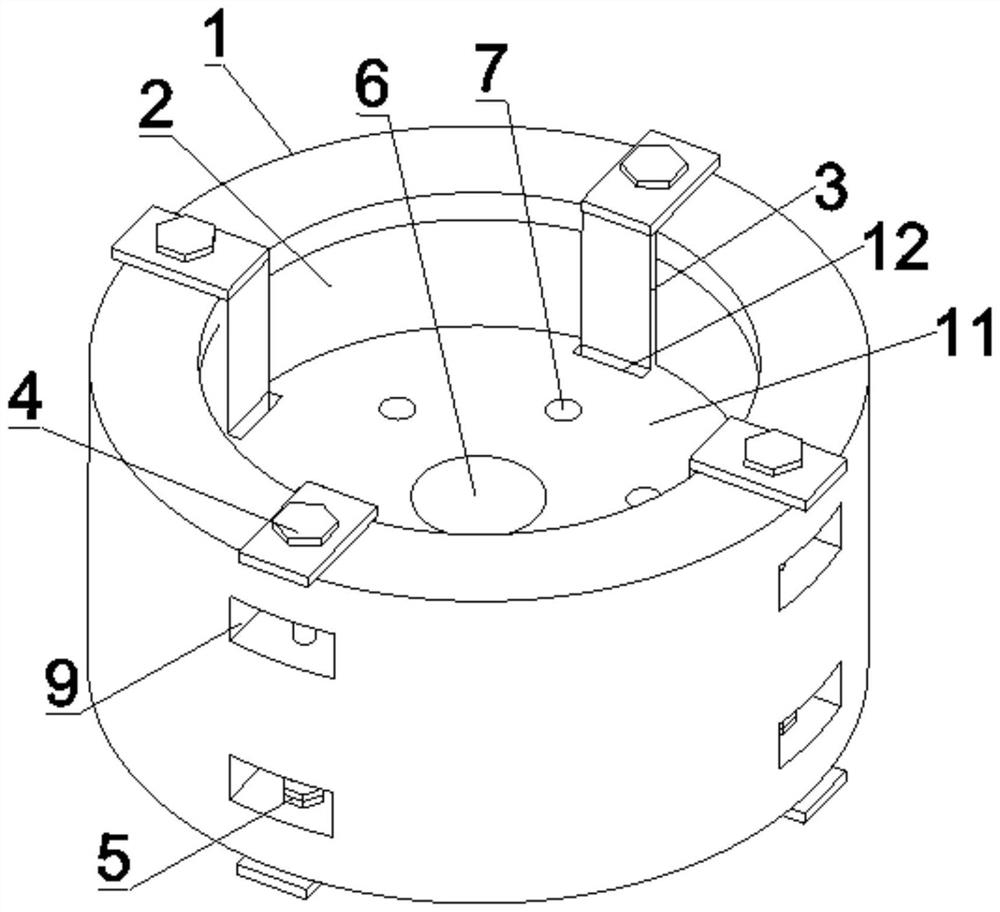
[0034] see Figure 1-7 As shown, the present embodiment is a brushless DC motor rotor, which includes a rotor housing 1 and a permanent magnet 2. The bottom end of the rotor housing 1 is provided with an end cover 6, and several permanent magnets 2 are annularly distributed on the inner wall of the rotor housing 1. There is a mortise and tenon structure between two adjacent permanent magnets 2, and it is fixed by a fixed frame 3. It should be noted that the fixed frame 3 is U-shaped, and the U-shaped fixed frame 3 is more convenient and quick to install, saving the cost of permanent magnets 2. fixed time.

[0035] The fixed frame 3 has the same shape as the position where two adjacent permanent magnets 1 abut against each other, which facilitates better fixing between the two permanent magnets 2 .

[0036] One side of the fixing frame 3 passes through the end cover 11 through the rectangular hole 12 between the end cover 11 and the rotor casing 1, and the upper and lower ends...

Embodiment 2

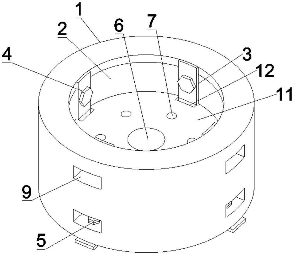
[0044] see Figure 1-7 As shown, the present embodiment is a brushless DC motor rotor, which includes a rotor housing 1 and a permanent magnet 2. The bottom end of the rotor housing 1 is provided with an end cover 6, and several permanent magnets 2 are annularly distributed on the inner wall of the rotor housing 1. There is a mortise and tenon structure between two adjacent permanent magnets 2, and it is fixed by a fixing frame 3. It should be noted that the fixing frame 3 is L-shaped, and the L-shaped fixing frame 3 makes the permanent magnet 2 be fixed more stably, and the The safety of the rotor during operation is ensured.

[0045] The fixed frame 3 has the same shape as the position where two adjacent permanent magnets 1 abut against each other, which facilitates better fixing between the two permanent magnets 2 .

[0046] One side of the fixing frame 3 passes through the end cover 11 through the rectangular hole 12 between the end cover 11 and the rotor casing 1, and th...


PUM


Abstract

The invention relates to the technical field of motors, in particular to a direct current brushless motor rotor and a forming method thereof. The direct current brushless motor rotor comprises a rotor shell and permanent magnets, an end cover is arranged at the bottom end of the rotor shell, an opening is formed in the top face of the rotor shell, the multiple permanent magnets are annularly distributed on the inner wall of the rotor shell, a mortise and tenon joint structure is formed between every two adjacent permanent magnets, the rotor is fixed through a fixing frame, and the fixing frame is fixed to the rotor shell through bolts and nuts. According to the invention, the bolt, a multi-nut structure and the fixing frame are used for fixing the permanent magnet, the phenomenon of glue failure caused by too high temperature in the rotor shell is avoided, and the stability of the permanent magnet is improved; and a plurality of fan blades are fixedly distributed on the rear end cover of the rotor shell, so that heat in the rotor shell is timely dissipated through rotation of the fan blades in the rotation process of the rotor shell, and the situation that the temperature in the shell is too high, and the magnetism of the permanent magnet is affected is prevented.

Description

technical field [0001] The invention relates to the technical field of motors, in particular to a DC brushless motor rotor and a forming method thereof. Background technique [0002] The brushless DC motor consists of a motor body and a driver, and is a typical mechatronic product. A brushless motor refers to a motor without a brush and a commutator (or slip ring), also known as a commutator-less motor. As early as the 19th century, when the motor was born, the practical motor produced was a brushless form, that is, an AC squirrel-cage asynchronous motor, which was widely used. However, asynchronous motors have many insurmountable defects, so that the development of motor technology is slow. Transistors were born in the middle of the last century, so brushless DC motors that use transistor commutation circuits instead of brushes and commutators came into being. This new brushless motor, called an electronically commutated DC motor, overcomes the shortcomings of the first ...

Claims


Application Information

Patent Timeline
Patent Type & Authority Applications(China)
IPC IPC(8): H02K29/00H02K1/28H02K5/20H02K9/06H02K15/03H02K1/27
CPCH02K29/00H02K1/28H02K5/20H02K9/06H02K15/03H02K1/2786
Inventor 彭东琨
Owner 安徽乐普电机有限公司
Why Eureka
Try Eureka