

Projectile shell separation structure
A technology for separating structures and rocket shells, which is applied in the field of spacecraft structures, can solve problems such as large separation and separation distances, easy interference problems, and complex separation structures, so as to reduce separation links, prevent interference between structures, and simple separation structures Effect
- Summary
- Abstract
- Description
- Claims
- Application Information
AI Technical Summary
Problems solved by technology
Method used
Image

Examples
Embodiment Construction
[0019] The present invention will be further described below in conjunction with accompanying drawing.
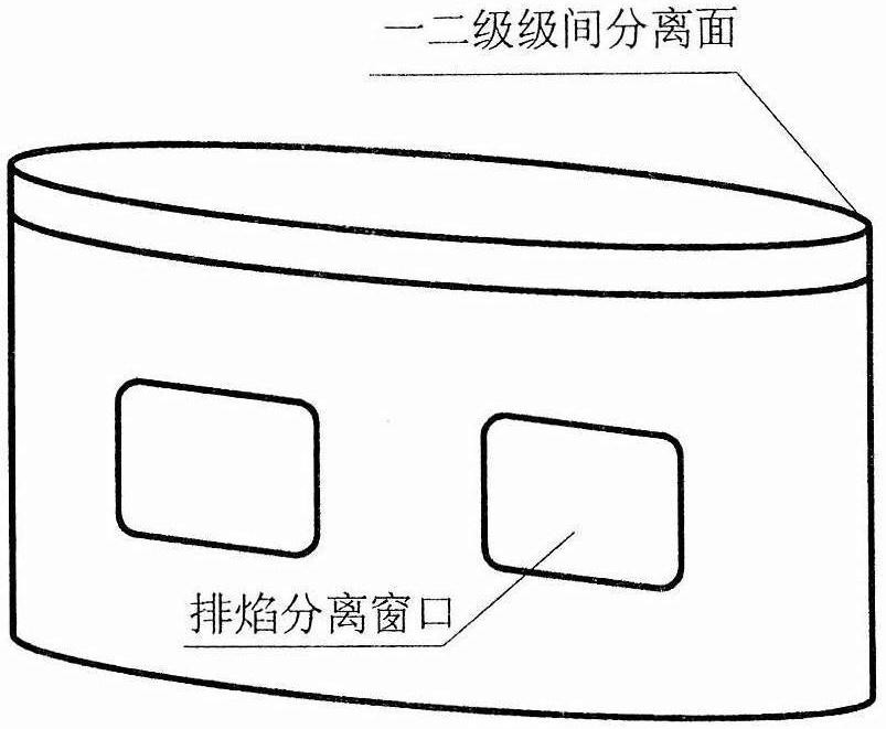
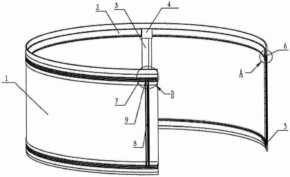
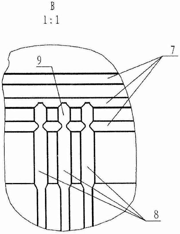
[0020] The separation structure of the rocket shell of the present invention is an annular closed structure, such as figure 2 Shown is a partial cross-sectional schematic view of the cutting and separating structure of the present invention. The separation structure of the missile case includes: a separation case 1 , a circumferential shield 2 , an axial shield 3 , a T-shaped shield 4 , a flexible detonating cord assembly 5 and a T-shaped explosion transfer assembly 6 . At the predetermined separation place outside the circumference of the separation shell 1, there are respectively circumferential preset weakening grooves 7, axial preset weakening grooves 8 and T-shaped prefabricated weakening grooves 9, as attached image 3 shown.
[0021] On the upper and lower end faces of the separation case 1 , the flexible detonating cord assembly 5 is installed in the position cor...
PUM
 Abstract
Description
Claims
Application Information