
Toilet mirror with cleaning function

A vanity mirror and functional technology, applied in the field of vanity mirrors, can solve problems such as hitting the reset coil box, affecting the service life of the reset coil box, and generating noise

Inactive Publication Date: 2021-07-06
PANZHIHUA UNIV
View PDF1 Cites 0 Cited by
  • Summary
  • Abstract
  • Description
  • Claims
  • Application Information

AI Technical Summary

Problems solved by technology

[0003] However, this structure has the following disadvantages: since the two ends of the movable crossbeam are respectively connected with two reset coil boxes, in the process of manually pulling the movable crossbeam to move downward, it is easy to cause the two ends of the movable crossbeam to be broken due to uneven force. end is not synchronized, which leads to the jamming of the movable beam
When the movable crossbeam is driven upward by the clockwork spring in the reset coil box, due to manufacturing, installation, wear and other reasons, the reset force provided by the clockwork spring in the two reset coil boxes will be different. The same, then it is easy to cause the two ends of the movable beam to be out of sync, which will cause the movable beam to be stuck; when the movable beam moves to the upper end of the frame, it is easy to cause the movable beam to hit the reset winding box, which not only produces noise , and affect the service life of the reset winding box

Method used


Image

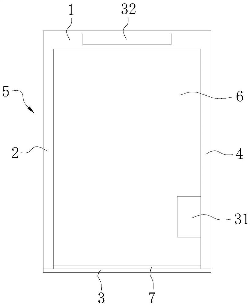
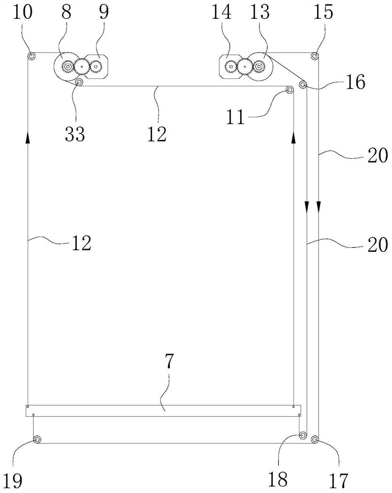
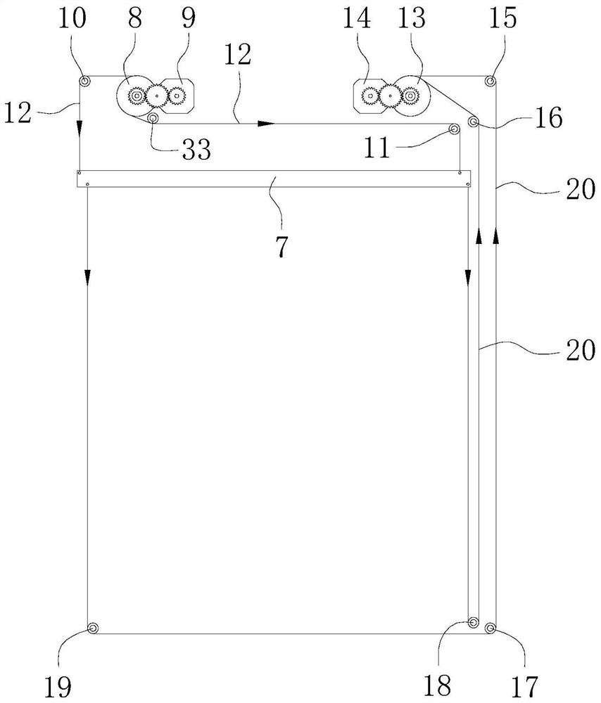
  • Toilet mirror with cleaning function
  • Toilet mirror with cleaning function
  • Toilet mirror with cleaning function

Examples


Embodiment approach

[0085] As an embodiment, the second drive mechanism may include a third motor fixed below the upper frame 1, and the other end is fixed on the output shaft of the third motor, and the other end is fixed to the upper end of the imaging mirror 6. When working, the third motor drives the output shaft to rotate, wrap the drawntrope on the output shaft of the third motor, and then pull the upper end of the imaging mirror 6 to pull down by drawing.

[0086] Preferably, continue to see Figure 9 to 13 The second drive mechanism includes a steering machine 28 and a drawn cord 29; the steering machine 28 is disposed on the back side of the imaging mirror 6, and is fixed below the upper frame 1; one end of the drawn cord 29 and the steering machine 28 The rocker arm is connected, and the other end is connected to the upper end of the imaging mirror 6.

[0087] The steering machine 28 is a power device, mainly including driving motor, reducer, rocker arm and position detecting element, etc., ...


PUM


Abstract

The invention belongs to the technical field of toilet mirrors and provides a toilet mirror with a cleaning function. The toilet mirror comprises a mirror frame, an imaging mirror mounted in the mirror frame, a cleaning brush and a first driving mechanism; the cleaning brush is arranged on the mirror surface of the imaging mirror and has two ends in sliding fit with a left frame and a right frame; the first driving mechanism is used for driving the cleaning brush to reciprocate between an upper frame and a lower frame; and the first driving mechanism comprises a first winding mechanism and a second winding mechanism. Through the cooperation of the first winding mechanism and the second winding mechanism, the cleaning brush is controlled to reciprocate between the upper frame and the lower frame so as to clean the mirror surface of the imaging mirror; the two ends of the cleaning brush can be simultaneously controlled to move towards the upper frame through a first motor of the first winding mechanism, and the two ends of the cleaning brush can be simultaneously controlled to move towards the lower frame through a second motor of the second winding mechanism, so that the synchronism of the two ends of the cleaning brush in the moving process is ensured; and therefore, the cleaning brush is prevented from being stuck in the moving process.

Description

Technical field [0001] The present invention relates to the technical field of dressing mirror, in particular a dressing mirror having a cleaning function. Background technique [0002] In the patent application of CN208541024U, the authorized publication is disclosed, which is disclosed, which is not easy to condense water vapor, which allows the rubber cleaning plate to be adjacent to the mirror of the imaging mirror before use, and make the beam through hand-held active beam The cleaning plate moves downward along the mirror, thereby cleaning the mirror of the imaging mirror. [0003] However, this structure has the following disadvantages: Since both ends of the active beam are connected to two reset roll boxes, then in the process of manually pulling the active beam, it is easy to cause the active beam due to the unevenness of the actuation. The end is not synchronized, which in turn leads to a phenomenon that the active beam appears. When moving the active beam moves upward...

Claims


Application Information

Patent Timeline
Patent Type & Authority Applications(China)
IPC IPC(8): A47G1/02A47L25/00
CPCA47G1/02A47L25/00
Inventor 谭科华
Owner PANZHIHUA UNIV
Learn More