Energy-saving automatic tea making machine
A tea making machine, automatic technology, applied in beverage preparation devices, household appliances, applications, etc., can solve the problems of steam waste, energy waste, etc.
- Summary
- Abstract
- Description
- Claims
- Application Information
AI Technical Summary
Problems solved by technology
Method used
Image
Examples
Embodiment 1
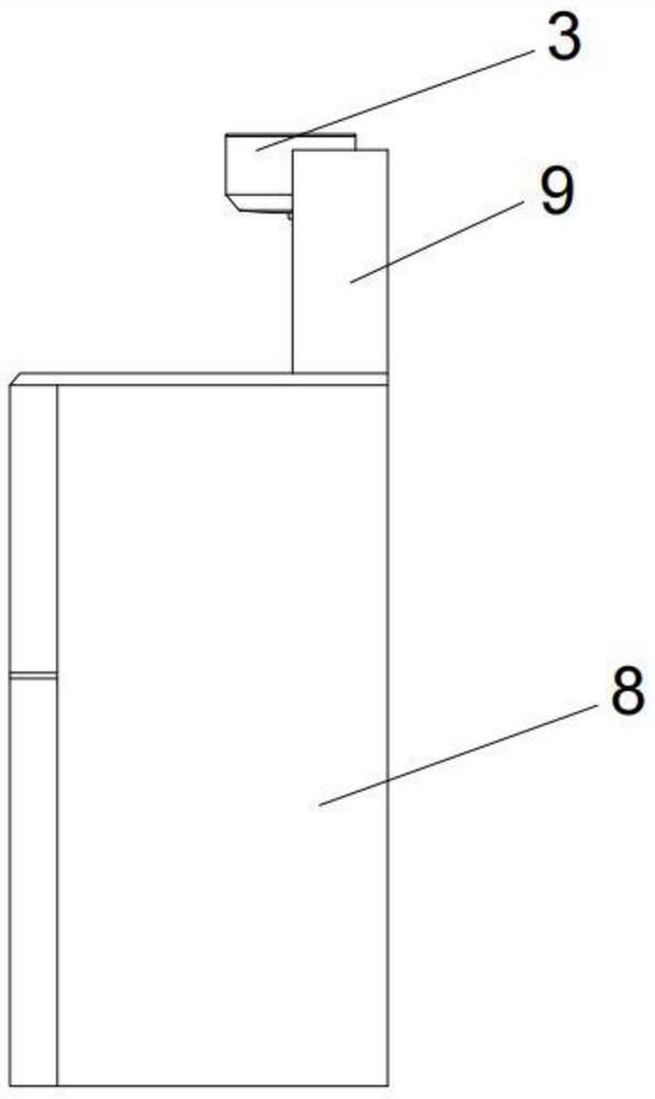
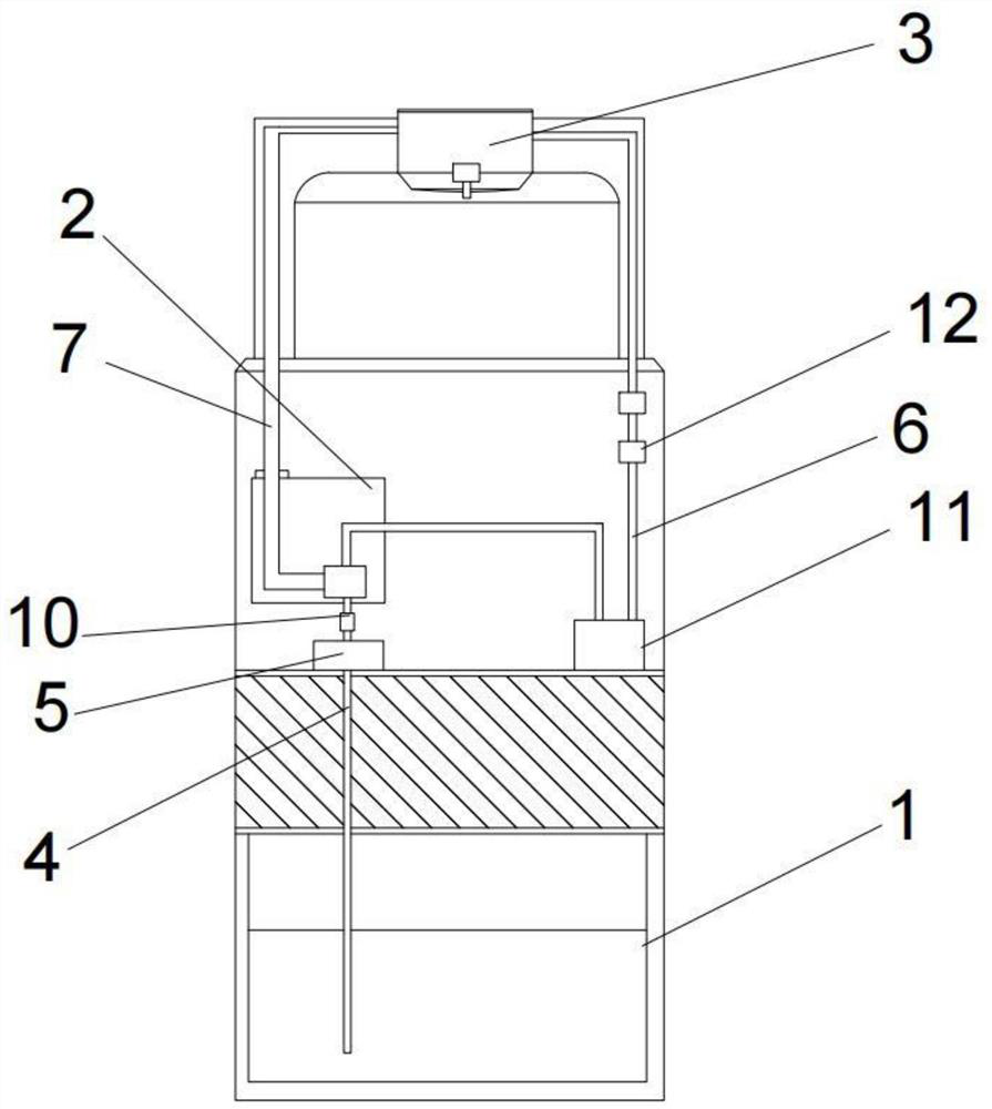
[0034] like figure 1 , figure 2 Shown, the technical scheme that the present invention takes is as follows:
[0035]An energy-saving automatic tea making machine, comprising: a water storage component 1, a hot water tank component 2, a hot water component 3 and a body 8; the hot water tank component is installed on the upper part of the water storage component, and the water storage component passes through a water inlet 4 Connected to the hot water tank assembly, the first water pump 5 is installed on the water inlet pipe; the water outlet pipe 6 is connected to the outside of the hot water tank unit; the hot water assembly is connected to the water outlet pipe; the fumigation pipeline 7 is installed on the top of the hot water assembly , the fumigation pipeline communicates with the hot water bladder assembly, and the steam generated by the hot water assembly is sent into the hot water bladder assembly through the fumigation pipeline for heating the water in the hot water ...
Embodiment 2
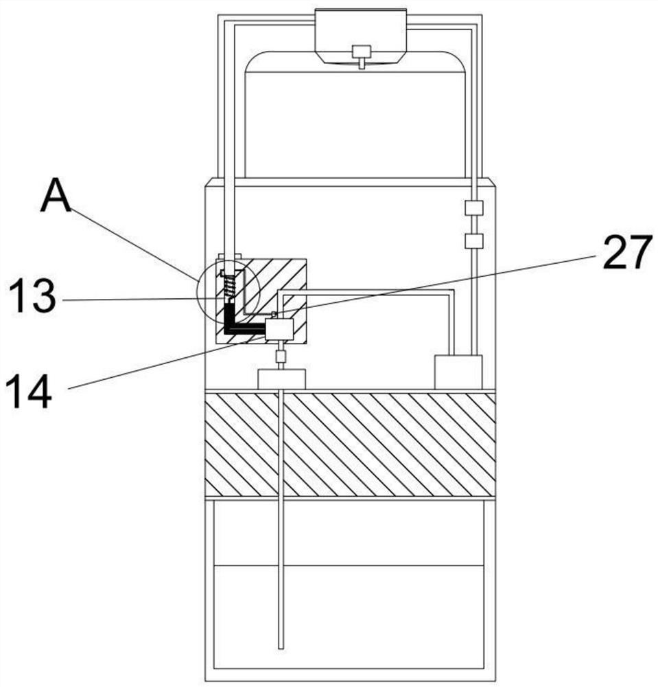
[0037] Such as image 3 , Figure 4 As shown, the difference between Embodiment 2 and Embodiment 1 is that the hot water tank assembly includes a heat exchange tube 13 and a tank body 14 communicating with the fumigation pipeline, and a fixing ring 15 is installed inside the heat exchange tube. A spiral coil 16 made of memory metal is installed under the ring. After the heating temperature of the spiral coil exceeds the transformation temperature of the memory metal, it will expand downward; the upper end of the spiral coil is connected to the outlet pipe through the return line 17, The lower end of the spiral coil tube is provided with a vertical extension pipe 18, the bottom of the heat exchange tube is equipped with a connecting part 19, and the top of the connecting part is provided with a V-shaped converging groove 20, and below the converging groove The area is equipped with a water inlet chamber 21, and a filter sheet 22 is fixed in the water inlet chamber, and the bot...
Embodiment 3
[0042] Such as Figure 5 , Image 6 , Figure 7 with Figure 8 As shown, the difference between Embodiment 3 and Implementation 2 is that the central bottom of the converging tank is provided with a side channel 31, the bottom of the side channel is connected to the water inlet chamber, and the side channel is equipped with a device that only allows water to flow to The one-way electromagnetic valve 33 that inflows downwards, the top of the one-way electromagnetic valve is equipped with a strip-shaped water drop detection assembly 34, and the water drop detection assembly includes a water receiving tank 35 whose top communicates with the outside, and potassium chloride wafers are housed in the water receiving tank , the potassium chloride wafer is covered with absorbent cotton 36; the two ends of the water receiving tank are equipped with conductive sheets 32 respectively, and the bottom of the water receiving tank is buried with a heating sheet 37, and the heating sheet con...
PUM
 Abstract
Description
Claims
Application Information
 - R&D
- Intellectual Property
- Life Sciences
- Materials
- Tech Scout
- Unparalleled Data Quality
- Higher Quality Content
- 60% Fewer Hallucinations
Browse by: Latest US Patents, China's latest patents, Technical Efficacy Thesaurus, Application Domain, Technology Topic, Popular Technical Reports.
© 2025 PatSnap. All rights reserved.Legal|Privacy policy|Modern Slavery Act Transparency Statement|Sitemap|About US| Contact US: help@patsnap.com


